MCP23017 IO Expansion Board
The MCP23017 adds 16 digital I/O pins to any microcontroller over two I2C wires, with interrupts and up to eight boards on one bus.
- I/O16 pins in two 8-bit ports; GPA7 and GPB7 output only
- Supply voltage1.8 V to 5.5 V
- I2C speed100 kHz (1.8 V and up), 400 kHz (2.7 V and up), 1.7 MHz (4.5 V and up)
- I2C address0x20 to 0x27 set by A2, A1, A0; up to 8 devices per bus
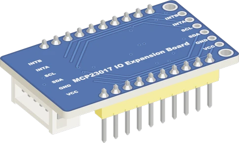
The MCP23017 is Microchip's 16-bit I/O expander: two 8-bit ports (GPA0 to GPA7, GPB0 to GPB7) controlled over I2C at 100 kHz, 400 kHz or 1.7 MHz, from a 1.8 V to 5.5 V supply (Microchip DS20001952D, pp. 1, 4). On Waveshare's board, wire VCC to the microcontroller's logic voltage, GND, SDA and SCL; the board pulls SDA and SCL up with 10 kΩ and pulls A0 to A2 high, so it answers at 0x27 until you bridge the address jumpers (Waveshare schematic; DS20001952D, p. 15). Each pin sinks or sources 25 mA at most (p. 3), and GPA7 and GPB7 are output only (p. 1).
The MCP23017 is a 16-bit I/O expander from Microchip with an I2C interface. Its 16 pins form two 8-bit ports, A and B, and every pin can be an input or an output with its own direction, polarity inversion, weak pull-up and interrupt-on-change setting (Microchip MCP23017/MCP23S17 datasheet DS20001952D, p. 1). Pins default to inputs at power-up. One exception matters to makers: since revision D of the datasheet, GPA7 and GPB7 are specified as output only on the MCP23017 (p. 1), so buttons and sensors belong on the other fourteen pins.
It runs from 1.8 V to 5.5 V and speaks I2C at 100 kHz, 400 kHz or 1.7 MHz (datasheet, pp. 1, 4); 400 kHz needs at least 2.7 V and 1.7 MHz at least 4.5 V (p. 6). Its 7-bit address is 0100 followed by the levels on pins A2, A1 and A0, so addresses 0x20 to 0x27 let up to eight expanders share one bus for 128 extra pins (pp. 1, 15). Two interrupt outputs, INTA for port A and INTB for port B, can be push-pull active-low, active-high or open-drain, and can be mirrored so either one reports both ports (p. 1).
Waveshare's MCP23017 IO Expansion Board puts the chip on a 38 × 23 mm board for 3.3 V or 5 V systems, with the I2C lines and both interrupts on a PH2.0 connector and on solder pads (Waveshare user manual, p. 2). Its schematic adds 10 kΩ pull-ups on SDA and SCL, 10 kΩ pull-ups on A0, A1 and A2 with solder jumpers to ground, a 10 kΩ pull-up with 100 nF on RESET, and a power LED. The chip itself sets the logic levels: powered from 3.3 V it talks 3.3 V I2C, powered from 5 V it talks 5 V.
MCP23017 IO Expansion Board pinout
| Pin | Function | Type |
|---|---|---|
| VCC_A | VCC (beside PA0)1.8–5 V | power in |
| GND_A | GND (beside PA0) | power in |
| PA0 | Digital | bidirectional |
| PA1 | Digital | bidirectional |
| PA2 | Digital | bidirectional |
| PA3 | Digital | bidirectional |
| PA4 | Digital | bidirectional |
| PA5 | Digital | bidirectional |
| PA6 | Digital | bidirectional |
| PA7 | Digital | bidirectional |
| VCC_B | VCC (beside PB7)1.8–5 V | power in |
| GND_B | GND (beside PB7) | power in |
| PB7 | Digital | bidirectional |
| PB6 | Digital | bidirectional |
| PB5 | Digital | bidirectional |
| PB4 | Digital | bidirectional |
| PB3 | Digital | bidirectional |
| PB2 | Digital | bidirectional |
| PB1 | Digital | bidirectional |
| PB0 | Digital | bidirectional |
| INTB | Digital | output |
| INTA | Digital | output |
| SCL | I2C SCL | bidirectional |
| SDA | I2C SDA | bidirectional |
| GND | GND (PH2.0 connector) | power in |
| VCC | VCC: 1.8-5.5 V (3.3 V or 5 V) (PH2.0 connector)1.8–5 V | power in |
| INTB_2 | Digital | output |
| INTA_2 | Digital | output |
| SCL_2 | I2C SCL | bidirectional |
| SDA_2 | I2C SDA | bidirectional |
| GND_2 | GND (2.54 mm pad) | power in |
| VCC_2 | VCC: 1.8-5.5 V (3.3 V or 5 V) (2.54 mm pad)1.8–5 V | power in |
How to wire the MCP23017 IO Expansion Board
Pin by pin, for the board you have.
| MCP23017 IO Expansion Board | Arduino Uno | Note |
|---|---|---|
| VCC | 5V | |
| GND | GND | |
| SDA | SDA | |
| SCL | SCL |
| MCP23017 IO Expansion Board | ESP32 DevKit V1 | Note |
|---|---|---|
| VCC | 3V3 | |
| GND | GND | |
| SDA | GPIO21 (D21) | |
| SCL | GPIO22 (D22) |
| MCP23017 IO Expansion Board | Raspberry Pi Pico | Note |
|---|---|---|
| VCC | 3V3 | |
| GND | GND | |
| SDA | GP4 | |
| SCL | GP5 |
MCP23017 IO Expansion Board code
Every example here compiles for its board.
// MCP23017 IO Expansion Board on Arduino Uno: wiring and a free simulation at https://www.tinkered.ai/components/mcp23017-io-expander
#include <Wire.h>
#include <Adafruit_MCP23X17.h>

// A button from PA0 to GND, an LED (with its resistor) on PB0.
const uint8_t BUTTON = 0;  // PA0
const uint8_t LED = 8;     // PB0
Adafruit_MCP23X17 mcp;

void setup() {
  Serial.begin(115200);
  if (!mcp.begin_I2C(0x27)) {
    Serial.println("MCP23017 not found at 0x27");
    while (1) delay(10);
  }
  mcp.pinMode(BUTTON, INPUT_PULLUP);
  mcp.pinMode(LED, OUTPUT);
}

void loop() {
  bool pressed = mcp.digitalRead(BUTTON) == LOW;
  mcp.digitalWrite(LED, pressed ? HIGH : LOW);
  delay(20);
}
// MCP23017 IO Expansion Board on ESP32 DevKit V1: wiring and a free simulation at https://www.tinkered.ai/components/mcp23017-io-expander
#include <Wire.h>
#include <Adafruit_MCP23X17.h>

// A button from PA0 to GND, an LED (with its resistor) on PB0.
const uint8_t BUTTON = 0;  // PA0
const uint8_t LED = 8;     // PB0
Adafruit_MCP23X17 mcp;

void setup() {
  Serial.begin(115200);
  if (!mcp.begin_I2C(0x27)) {
    Serial.println("MCP23017 not found at 0x27");
    while (1) delay(10);
  }
  mcp.pinMode(BUTTON, INPUT_PULLUP);
  mcp.pinMode(LED, OUTPUT);
}

void loop() {
  bool pressed = mcp.digitalRead(BUTTON) == LOW;
  mcp.digitalWrite(LED, pressed ? HIGH : LOW);
  delay(20);
}
// MCP23017 IO Expansion Board on Raspberry Pi Pico: wiring and a free simulation at https://www.tinkered.ai/components/mcp23017-io-expander
#include <Wire.h>
#include <Adafruit_MCP23X17.h>

// A button from PA0 to GND, an LED (with its resistor) on PB0.
const uint8_t BUTTON = 0;  // PA0
const uint8_t LED = 8;     // PB0
Adafruit_MCP23X17 mcp;

void setup() {
  Serial.begin(115200);
  if (!mcp.begin_I2C(0x27)) {
    Serial.println("MCP23017 not found at 0x27");
    while (1) delay(10);
  }
  mcp.pinMode(BUTTON, INPUT_PULLUP);
  mcp.pinMode(LED, OUTPUT);
}

void loop() {
  bool pressed = mcp.digitalRead(BUTTON) == LOW;
  mcp.digitalWrite(LED, pressed ? HIGH : LOW);
  delay(20);
}
// MCP23017 IO Expansion Board on STM32 Blue Pill (F103C8): wiring and a free simulation at https://www.tinkered.ai/components/mcp23017-io-expander
#include <Arduino.h>
#include <Wire.h>
#include <Adafruit_MCP23X17.h>

Adafruit_MCP23X17 mcp;

const uint8_t LED_IO = 0;      // the expander's pin 0: PA0
const uint8_t BUTTON_IO = 8;   // the expander's pin 8: PB0 (to GND)

void setup() {
  Serial.begin(115200);
  if (!mcp.begin_I2C(0x27)) {   // 0x27: the board's jumpers open
    Serial.println("MCP23017 not found: check VCC, SDA/SCL and its address jumpers");
    while (true) delay(10);
  }
  mcp.pinMode(LED_IO, OUTPUT);
  mcp.pinMode(BUTTON_IO, INPUT_PULLUP);
}

void loop() {
  bool pressed = mcp.digitalRead(BUTTON_IO) == LOW;
  mcp.digitalWrite(LED_IO, pressed ? HIGH : LOW);
  Serial.println(pressed ? "button pressed" : "button released");
  delay(100);
}
Before you wire it
- VCC to the board's logic supply (5V on an Uno, 3V3 on an ESP32, a Pico, an STM32), GND to GND. Wire SDA/SCL to its I2C pins (Uno A4/A5, ESP32 GPIO21/22, Pico GP4/GP5, Nucleo D14/D15, NodeMCU D2/D1). No extra pull-ups: the board has 10 kΩ on both.
- An LED on an output always has its resistor (220-470 Ω) in series.
- A button goes from an input pin to GND, and the sketch sets that pin INPUT_PULLUP: it reads LOW pressed, HIGH released. No external resistor is needed.
- Buttons and sensors on PA0-PA6 and PB0-PB6 only; PA7 and PB7 for outputs.
- In code: mcp.begin_I2C(0x27), using the address the jumpers set. Check it returned true. Then mcp.pinMode(n, OUTPUT | INPUT | INPUT_PULLUP), mcp.digitalWrite(n,...) and mcp.digitalRead(n), with n 0-15.
- Wire INTA to an interrupt-capable MCU pin set INPUT_PULLUP;
- Call mcp.setupInterrupts(true, false, LOW) (mirrored, push-pull, active LOW) and mcp.setupInterruptPin(n, CHANGE) per pin;
- In the ISR only set a flag; in loop() call mcp.getLastInterruptPin() then mcp.clearInterrupts() (I2C never runs inside the ISR).
- Two boards: each its own address (jumpers and addr=), each its own Adafruit_MCP23X17 object.
- Beside an I2C LCD (its PCF8574 backpack is 0x27 too): give the board another address, e.g. addr=0x20 (all three jumpers bridged) and mcp.begin_I2C(0x20).
- No VCC at 5 V on a 3.3 V board: the board's pull-ups would put 5 V on SDA and SCL.
- No LED straight on a pin without its resistor; no motor, relay coil or buzzer straight on a pin (25 mA): drive a module or a transistor.
- No buttons or sensors on PA7 or PB7.
- No I2C calls (mcp.digitalRead, getLastInterruptPin) inside an interrupt handler.
- No Adafruit_MCP23017 (the library's old class from version 1): use Adafruit_MCP23X17.
- Power VCC from the microcontroller's logic supply: 5 V on an Uno, 3.3 V on an ESP32, Pico or STM32. The board's 10 kΩ pull-ups take SDA and SCL to VCC (Waveshare schematic), and the chip needs 0.8 × VDD for a high on SCL and SDA (DS20001952D, p. 4), 4.0 V at a 5 V supply, which a 3.3 V board cannot reliably give.
- Wire SDA and SCL to the board's I2C pins (Uno A4 and A5, ESP32 GPIO21 and GPIO22, Pico GP4 and GP5). The board already has 10 kΩ pull-ups (schematic), so add none.
- The address is 0100 A2 A1 A0 (DS20001952D, p. 15). With the jumpers open the board pulls all three high, giving 0x27; bridging a jumper grounds that bit, down to 0x20 with all three bridged (Waveshare schematic and wiki).
- Each pin sinks or sources 25 mA at most, and the whole chip 125 mA into VDD (DS20001952D, p. 3): give every LED a series resistor and drive motors, relays and buzzers through a transistor or module.
- Use GPA7 and GPB7 only as outputs; Microchip specifies them as output only on the MCP23017 (DS20001952D, p. 1).
- For buttons, wire them from the pin to GND and enable the internal 100 kΩ pull-up (DS20001952D, p. 22); the pin reads low when pressed.
Specifications
- I/O
- 16 pins in two 8-bit ports; GPA7 and GPB7 output onlyMicrochip DS20001952D, p. 1
- Supply voltage
- 1.8 V to 5.5 VMicrochip DS20001952D, p. 4
- I2C speed
- 100 kHz (1.8 V and up), 400 kHz (2.7 V and up), 1.7 MHz (4.5 V and up)Microchip DS20001952D, pp. 1, 6
- I2C address
- 0x20 to 0x27 set by A2, A1, A0; up to 8 devices per busMicrochip DS20001952D, pp. 1, 15
- Pin current
- 25 mA max sunk or sourced per pin; 125 mA into VDD; 150 mA out of VSSMicrochip DS20001952D, p. 3 (absolute maximum)
- Input high threshold
- 0.8 × VDD on GPIO, SCL, SDA and RESETMicrochip DS20001952D, p. 4
- Weak pull-ups
- 100 kΩ per pin, enabled in GPPU; 40 to 115 µA at 5 VMicrochip DS20001952D, pp. 4, 22
- Standby current
- 1 µA max (-40 to 85 °C)Microchip DS20001952D, p. 4
- Board pull-ups
- 10 kΩ on SDA and SCL; 10 kΩ on A0, A1, A2 (jumpers to GND); 10 kΩ on RESETWaveshare MCP23017 IO Expansion Board schematic
- Board size
- 38 × 23 mm, 2.0 mm mounting holesWaveshare MCP23017 IO Expansion Board user manual, p. 2
- Maximum supply voltage
- 5.5 V
- Interface
- I2C
- On-board I2C pull-ups
- Yes (10 kΩ)
- Dimensions
- 38 × 23 × 11.6 mm
- Weight
- 4 g
From the Waveshare (Microchip MCP23017-E/SS)'s datasheet, published by Waveshare (Microchip MCP23017-E/SS).
Common mistakes
Buttons on GPA7 or GPB7
Microchip's datasheet specifies GPA7 and GPB7 as output only on the MCP23017 (DS20001952D, p. 1). An input there may read wrong. Move buttons and sensors to GPA0 to GPA6 or GPB0 to GPB6.
Address clash with an I2C LCD
Waveshare's board answers at 0x27 with its jumpers open, the same address as many PCF8574 LCD backpacks. Bridge one or more address jumpers to move it within 0x20 to 0x26 (DS20001952D, p. 15) and use the same address in the sketch.
5 V supply on a 3.3 V board
The board's I2C pull-ups go to VCC, so at 5 V they put 5 V on the 3.3 V board's SDA and SCL, and the chip wants 4.0 V for a high at that supply (DS20001952D, p. 4). Power it from 3.3 V on a 3.3 V board.
Overloading the pins
25 mA per pin and 125 mA for the whole chip are absolute maximum ratings (DS20001952D, p. 3), not working currents. Sixteen LEDs at 10 mA already exceed the chip's total; use larger resistors or transistors.
Interrupt fires once and never again
The interrupt condition clears only when the GPIO or INTCAP register is read (DS20001952D, p. 25). Read one of them after each interrupt, and do the I2C read in loop(), not inside the interrupt handler.
MCP23017 IO Expansion Board questions
How do I connect the MCP23017 to an Arduino?
Wire VCC to 5 V, GND to GND, SDA to A4 and SCL to A5 on an Uno. The Waveshare board already has 10 kΩ pull-ups on both lines (schematic) and answers at 0x27 with its jumpers open (DS20001952D, p. 15). In the Adafruit MCP23017 Arduino library, call begin_I2C(0x27), then pinMode, digitalWrite and digitalRead with pins 0 to 15, where 0 to 7 are port A and 8 to 15 port B.
Can I use the MCP23017 with an ESP32 or Raspberry Pi Pico at 3.3 V?
Yes: power the board from 3.3 V. The chip runs from 1.8 V to 5.5 V (DS20001952D, p. 4), and powering it from 3.3 V keeps the board's SDA and SCL pull-ups at 3.3 V. Powered from 5 V, it would need 4.0 V for an I2C high (0.8 × VDD, p. 4).
What I2C address does the MCP23017 use?
0x20 to 0x27: the address is 0100 followed by the levels on A2, A1 and A0 (DS20001952D, p. 15). Waveshare's board pulls all three high, so it answers at 0x27 until you bridge jumpers to ground (Waveshare schematic). Up to eight can share one bus (p. 1).
Why does my MCP23017 not respond on I2C?
Run an I2C scanner first. If nothing appears, check VCC, GND, and that SDA and SCL are on the board's I2C pins, not swapped. If a device appears at another address, the address jumpers set A2, A1, A0 differently from your sketch (DS20001952D, p. 15). The RESET pin must also be held high; the Waveshare board does this with a 10 kΩ pull-up (schematic).
How much current can an MCP23017 pin supply?
25 mA sunk or sourced per pin, with 125 mA into VDD and 150 mA out of VSS for the whole chip, as absolute maximum ratings (DS20001952D, p. 3). An LED at 5 to 10 mA through a resistor is fine; a motor, relay coil or buzzer needs a transistor.
MCP23017 vs PCF8574: which I/O expander should I use?
The MCP23017 gives 16 pins with true push-pull outputs, per-pin direction, 100 kΩ pull-ups and two configurable interrupt outputs (DS20001952D, p. 1). The PCF8574 gives 8 quasi-bidirectional pins (TI PCF8574 datasheet SCPS068K, p. 1) and is the chip on most I2C LCD backpacks. Choose the MCP23017 when you need more pins, real outputs or interrupts per port.
Build something with the MCP23017 IO Expansion Board
- Build this
16-button control panel
Read up to 14 buttons with internal pull-ups and use the two output-only pins for status LEDs, all on two I2C wires.
- Build this
Relay or LED bank controller
Drive a bank of relay modules or LEDs through transistors from one expander, or eight expanders on one bus.
- Build this
Keypad or rotary encoder interface
Use interrupt-on-change on INTA and INTB so the microcontroller reacts to key presses without polling.
- Build this
Pin expansion for an ESP32 or Pico
Free up the board's own GPIOs for SPI displays and radios by moving slow switches and indicators to the MCP23017.
This page as plain Markdown, for ChatGPT, Claude or your own agent. /components/mcp23017-io-expander.md