Arduino 'Blink' LED
The canonical first circuit: a 220-ohm resistor in series with an LED from a digital pin to ground, holding current to a safe ~13mA on 5V logic.
A 220-ohm fixed resistor, a standard E24 value most often used to current-limit an LED on a 5V line.

The 220-ohm resistor is a two-terminal fixed passive that sets or limits current by Ohm's law (V = I x R). At this 6.3mm by 2.5mm axial body size it is typically a 1/4W (0.25W) carbon film part, matching Yageo's CFR-25 family. 220 ohms is a standard E24 (and E12/E6) preferred value, so it is stocked everywhere and shows up in nearly every hobby kit.
It is non-polarized: neither lead has a defined polarity, so it can be soldered or inserted in either orientation. On a 4-band carbon film part the value reads Red-Red-Brown-Gold, where gold marks the common +/-5% tolerance (so an in-spec part measures roughly 209 to 231 ohms). Precision metal film versions of the same value are offered at +/-1%.
Its signature job is limiting current to an LED. From a 5V logic pin driving a ~2V red LED, 220 ohms passes about 13.6mA; from 3.3V the same LED sees about 5.9mA, both safely inside a typical LED's rating. The CFR-25 body is rated to a 250V maximum working voltage, but the binding limit in practice is power: dissipation is V-squared / R, so a 1/4W part is fully loaded near 7.4V across it.
Verified from the Tinkered component library.
Resistors are not polarized. Unlike LEDs or diodes, a 220-ohm resistor works identically either way around, so there is no correct orientation to line up.
Red-Red-Brown-Gold is 220 ohms. Swapping the third band to Red (Red-Red-Red) gives 2,200 ohms (2.2k), which starves an LED to a fraction of its intended brightness. Confirm the multiplier band before building.
220 ohms is tuned for LEDs on 3.3V to 5V logic. Dropping the same value across a 12V or 24V rail can exceed the 1/4W rating and cook the part; recompute R and the required power rating for the actual voltage.
Putting several LEDs in parallel behind a single 220-ohm resistor lets the LED with the lowest forward voltage hog the current and leaves the others dim. Give each LED its own series resistor.
Blue and white LEDs have a higher forward voltage than red, so 220 ohms passes less current through them. If a specific brightness or current matters, size the resistor to that LED's forward voltage rather than defaulting to 220 ohms.
The canonical first circuit: a 220-ohm resistor in series with an LED from a digital pin to ground, holding current to a safe ~13mA on 5V logic.
Power, activity, and fault LEDs on breadboards and PCBs almost always pair a single LED with a 220-ohm to 330-ohm series resistor.

resistor-1kCustom resistance values supported

resistor-10kCustom resistance values supported
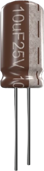
capacitor-ceramicCustom capacitance values supported
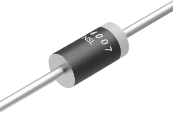
diode-1n4007General-purpose rectifier
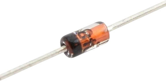
diode-1n4148Fast switching diode
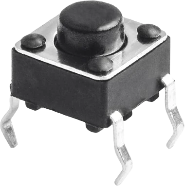
push-buttonMomentary digital input
Drop the 220Ω Resistor into a circuit, write firmware, and simulate it in your browser, then deploy to real hardware. All in one editable Tinkered project.