Design the circuit. Then prove it works.
Draw it yourself or describe what you need. Either way you get a schematic you can probe, measure, and run real firmware against, before you order a single part.
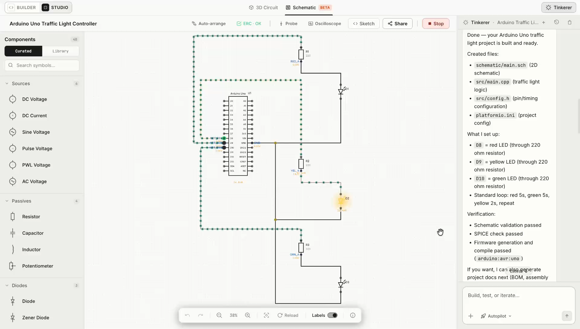
See the code and the circuit on one timeline.
Most tools make you choose. Run the firmware and guess at the analog, or simulate the analog with no firmware in it. Tinkered runs both together and measures them against a single clock, so you can watch a pin change state and watch what that did to your circuit in the same moment.
- Firmware
Your compiled code, running
The sketch that will ship runs against the circuit you drew. Pin writes, timers, and interrupts happen when the firmware says they happen.
- Analog
Real component behavior
Capacitors charge, op-amps settle, and dividers load exactly as their values dictate. Not animated approximations of a circuit.
- One timeline
Cause next to effect
Both are measured against the same clock, so a pin edge and the analog transient it caused appear on the same trace, at the same instant.
Measure it before you build it.
A schematic that only looks right is a guess. Tinkered gives the design a bench: probes on any net, a triggering oscilloscope, the analyses you already work in, and measurements that agree with what an instrument on your desk would tell you.
Oscilloscope
Probe any net or pin. Edge triggering with adjustable level, slope, hold-off, and pre-trigger position. Auto, normal, and single-shot capture, so a one-time event stays on screen.
Automatic measurements
Vpp, Vrms, Vavg, top and base, frequency, period, duty cycle, rise and fall time, and overshoot. Levels come from the settled waveform, not from peaks, so a ringing edge reports honest numbers.
Analysis modes
Operating point for a quick DC answer, transient for behavior over time, DC sweep for a curve across an input, and AC sweep for frequency response across decades.
Math and spectrum
Derive current across a shunt or instantaneous power from two probes. Take an FFT of any channel with selectable windowing when you need the frequency picture instead of the time one.
Protocol decode
Read UART, I2C, and SPI traffic decoded from the captured lines, so a bus problem is legible as frames instead of a wall of edges.
Design checks and export
Rule checks flag floating inputs, conflicting drivers, and power problems before you order parts. Export any capture as CSV when the analysis continues somewhere else.
Every capture is inspectable. Open the generated netlist and read exactly what was solved, line by line.
From schematic to a device that runs.
Tinkered keeps the circuit from becoming an isolated drawing. For MCU projects, components, connections, and pin assignments continue into firmware, simulation, and physical hardware.
- 01
Create
Turn requirements into an editable circuit with components, values, nets, and power connections.
- 02
Validate
Review electrical conditions, missing connections, and unresolved requirements before moving on.
- 03
Connect firmware
Carry MCU interfaces and pin assignments into the board-specific code that controls the circuit.
- 04
Simulate
Run the firmware with the circuit and observe how inputs, outputs, and components respond together.
- 05
Build
Take the reviewed project toward assembly, deployment, and another physical iteration.
Questions about circuit design?
Still working through the circuit? Bring it to the maker community.
Join the communityWhat can Tinkered create from a circuit description?
Tinkered can turn a written requirement into an editable circuit schematic with components, symbols, electrical values, power connections, interfaces, nets, and pin assignments. You can inspect the result, change any decision, and continue refining the same design.
Is an AI-generated schematic still editable?
Yes. The schematic remains a structured engineering document rather than a flattened image. You can replace components, change values, reroute connections, revise power requirements, and update microcontroller pins directly.
How does Tinkered validate a circuit schematic?
Tinkered checks the design context around connections, electrical requirements, component interfaces, and pin assignments. It surfaces unresolved requirements and compatibility conflicts before simulation, so you can correct them while the schematic is still easy to change.
Can I create a circuit without a microcontroller?
Yes. You can create and edit schematics for circuits that do not include a microcontroller. When a design does include a supported MCU, Tinkered can also carry its components, connections, interfaces, and pin map into board-specific firmware and simulation.
How do schematics connect to Arduino, ESP32, or Raspberry Pi Pico firmware?
The circuit and firmware reference the same device model. Component interfaces, schematic nets, board pins, and firmware definitions stay related, so a hardware change can surface the code and configuration that may also need attention. Learn more about circuit and firmware development.
What kind of simulation can I run on a schematic?
You can solve the operating point for a quick DC answer, run a transient to see behavior over time, sweep a DC input to plot a curve, and sweep frequency for an AC response. Probe any net, trigger on an edge, and read automatic measurements such as frequency, duty cycle, rise time, and RMS. Captures export as CSV.
Can I simulate firmware and analog circuitry at the same time?
Yes, and they share one clock. Your compiled firmware runs against the circuit you drew, and both are measured on the same timeline, so a pin changing state and the analog transient it caused line up on the same trace. That is what makes it possible to debug a timing problem and a component problem in the same view instead of guessing which one you are looking at. See circuit and firmware simulation.
Is this accurate enough for real engineering work?
The analog side solves your actual component values rather than animating an approximation, and measurements follow the same definitions a bench instrument uses, so settled levels come from the waveform rather than from peaks. You can open the generated netlist and read exactly what was solved, line by line. Nothing about the result is hidden from you.
Can I design a circuit without using the AI agent?
Yes. You can start with a blank schematic, place components, draw connections, assign values, and configure pins yourself. The AI agent is optional, so you can use it for assistance when useful or work directly in the schematic editor from start to finish.
Which electronic components and development boards are supported?
Tinkered includes microcontrollers, sensors, displays, motors, drivers, communication modules, passives, and other common electronics components. Its broader workflow supports more than 1,300 development boards across Arduino, ESP32, Raspberry Pi Pico, RP2040, STM32, Teensy, micro:bit, nRF52, and Feather families. Browse the supported components library.
What can I do after the schematic is complete?
You can continue developing MCU firmware, run the connected design in simulation, revise the circuit from the observed behavior, and then move supported projects onto physical hardware. The schematic remains part of the project throughout that workflow instead of becoming a disconnected export.
Start your next circuit.
Create an editable schematic from a blank canvas or with AI assistance, validate the design, and carry MCU projects into firmware and simulation.