MCP23017 IO Expansion Board with an ESP32 DevKit V1
The MCP23017 adds 16 digital I/O pins to any microcontroller over two I2C wires, with interrupts and up to eight boards on one bus.
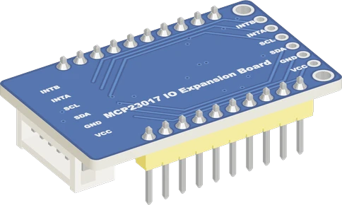
The MCP23017 board runs from the ESP32 DevKit V1's 3V3 with SDA on GPIO21 and SCL on GPIO22, and the sketch opens it at 0x27. It gives an ESP32 project sixteen more I/O pins over two wires, at the ESP32's own 3.3 V logic.
Wiring the MCP23017 IO Expansion Board to the ESP32 DevKit V1
Pin by pin.
| MCP23017 IO Expansion Board | ESP32 DevKit V1 |
|---|---|
| VCC | 3V3 |
| GND | GND |
| SDA | GPIO21 (D21) |
| SCL | GPIO22 (D22) |
What to know on the ESP32 DevKit V1
- Keep VCC on 3V3. The board's 10 kOhm pull-ups go to VCC, and the chip wants 0.8 x VDD for a high on SDA and SCL: on a 5 V VDD that is 4 V, more than an ESP32 can drive.Microchip MCP23017 datasheet DS20001952D, p. 4; Waveshare MCP23017 IO Expansion Board schematic
- At 3.3 V the chip runs I2C at up to 400 kHz; its 1.7 MHz mode needs 4.5 V or more, so do not raise Wire's clock past 400 kHz on this setup.Microchip MCP23017 datasheet DS20001952D, pp. 1, 6
- For interrupts, wire INTA to an ESP32 GPIO with INPUT_PULLUP. Avoid GPIO34 to GPIO39 there unless you add an external pull-up: they have no internal pull resistors.Espressif ESP32 Series Datasheet v5.3, p. 61
- The default 0x27 is also an I2C LCD backpack's address. Bridge the board's jumpers for another address (0x20 to 0x27) when both share the ESP32's bus.Microchip MCP23017 datasheet DS20001952D, pp. 1, 15
MCP23017 IO Expansion Board code for the ESP32 DevKit V1
Compiled for esp32:esp32:esp32 on 2026-10-30.
// MCP23017 IO Expansion Board on ESP32 DevKit V1: wiring and a free simulation at https://www.tinkered.ai/components/mcp23017-io-expander/esp32
#include <Wire.h>
#include <Adafruit_MCP23X17.h>

// A button from PA0 to GND, an LED (with its resistor) on PB0.
const uint8_t BUTTON = 0;  // PA0
const uint8_t LED = 8;     // PB0
Adafruit_MCP23X17 mcp;

void setup() {
  Serial.begin(115200);
  if (!mcp.begin_I2C(0x27)) {
    Serial.println("MCP23017 not found at 0x27");
    while (1) delay(10);
  }
  mcp.pinMode(BUTTON, INPUT_PULLUP);
  mcp.pinMode(LED, OUTPUT);
}

void loop() {
  bool pressed = mcp.digitalRead(BUTTON) == LOW;
  mcp.digitalWrite(LED, pressed ? HIGH : LOW);
  delay(20);
}
MCP23017 IO Expansion Board on the ESP32 DevKit V1: questions
Why add an MCP23017 to an ESP32 that already has many pins?
The DevKit V1 loses pins to strapping (GPIO0, 2, 5, 12, 15, ESP32 datasheet p. 22), to its flash (GPIO6 to 11, WROOM-32 datasheet p. 10) and to input-only GPIO34 to 39. The MCP23017 adds 16 general pins on GPIO21 and GPIO22.
Can MCP23017 pins drive a relay from the ESP32?
Not directly: each pin is limited to 25 mA (Microchip datasheet, p. 3). Drive a relay module or a transistor from it, as you would from the ESP32.
Keep going
This guide as plain Markdown. /components/mcp23017-io-expander/esp32.md