MCP23017 IO Expansion Board with a Raspberry Pi Pico
The MCP23017 adds 16 digital I/O pins to any microcontroller over two I2C wires, with interrupts and up to eight boards on one bus.
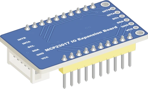
The MCP23017 board adds 16 I/O pins to the Raspberry Pi Pico over I2C0 (SDA GP4, SCL GP5), powered from 3V3 at address 0x27. Powered from the Pico's 3.3 V, its pull-ups and its I2C high threshold both sit at the Pico's level.
Wiring the MCP23017 IO Expansion Board to the Raspberry Pi Pico
Pin by pin.
| MCP23017 IO Expansion Board | Raspberry Pi Pico |
|---|---|
| VCC | 3V3 |
| GND | GND |
| SDA | GP4 |
| SCL | GP5 |
What to know on the Raspberry Pi Pico
- The chip needs 0.8 x VDD for a high on SDA and SCL. At 3.3 V that is about 2.6 V, which the Pico's pins give; at 5 V it would be 4.0 V, which they cannot.Microchip DS20001952D, p. 4
- Each expander pin sinks or sources 25 mA at most and the chip takes 125 mA into VDD in total; LEDs on its pins draw from the Pico's 3V3 rail, whose recommended limit is 300 mA.Microchip DS20001952D, p. 3; Raspberry Pi Pico datasheet, release 21, p. 8
- Waveshare's board answers at 0x27 until its address jumpers are bridged, the same address as most I2C LCD backpacks: on a shared Pico bus move one of them, for example to 0x20.Waveshare MCP23017 IO Expansion Board schematic; Microchip DS20001952D, p. 15
- To use its interrupt output, wire INTA to a Pico GPIO set INPUT_PULLUP and do the I2C reads in loop(), never inside the interrupt handler.Microchip MCP23017 datasheet, interrupt logic (INTA, INTB)
MCP23017 IO Expansion Board code for the Raspberry Pi Pico
Compiled for rp2040:rp2040:rpipico on 2026-10-30.
// MCP23017 IO Expansion Board on Raspberry Pi Pico: wiring and a free simulation at https://www.tinkered.ai/components/mcp23017-io-expander/raspberry-pi-pico
#include <Wire.h>
#include <Adafruit_MCP23X17.h>

// A button from PA0 to GND, an LED (with its resistor) on PB0.
const uint8_t BUTTON = 0;  // PA0
const uint8_t LED = 8;     // PB0
Adafruit_MCP23X17 mcp;

void setup() {
  Serial.begin(115200);
  if (!mcp.begin_I2C(0x27)) {
    Serial.println("MCP23017 not found at 0x27");
    while (1) delay(10);
  }
  mcp.pinMode(BUTTON, INPUT_PULLUP);
  mcp.pinMode(LED, OUTPUT);
}

void loop() {
  bool pressed = mcp.digitalRead(BUTTON) == LOW;
  mcp.digitalWrite(LED, pressed ? HIGH : LOW);
  delay(20);
}
MCP23017 IO Expansion Board on the Raspberry Pi Pico: questions
Does the MCP23017 work at 3.3 V with a Raspberry Pi Pico?
Yes. It runs from 1.8 V to 5.5 V (Microchip DS20001952D, p. 4); on 3V3 its pull-ups and 0.8 x VDD input threshold match the Pico's 3.3 V I2C.
Why do GPA7 and GPB7 not read my buttons?
They are output-only on current MCP23017 parts (Microchip DS20001952D, p. 1). Use PA0 to PA6 and PB0 to PB6 for inputs.
How many MCP23017 boards can a Pico control?
Eight per bus, at 0x20 to 0x27 (Microchip DS20001952D, p. 15), and the Pico has a second I2C controller (Pico datasheet, p. 4) for more.
Keep going
This guide as plain Markdown. /components/mcp23017-io-expander/raspberry-pi-pico.md