MCP23017 IO Expansion Board with an Arduino Uno
The MCP23017 adds 16 digital I/O pins to any microcontroller over two I2C wires, with interrupts and up to eight boards on one bus.
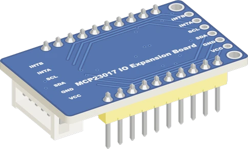
An Arduino Uno has twelve free digital pins once D0 and D1 serve USB, and the MCP23017 adds sixteen more over the two I2C pins, A4 and A5. Powered from the Uno's 5V, its pull-ups and logic levels match the Uno, and Waveshare's board answers at 0x27 out of the box.
Wiring the MCP23017 IO Expansion Board to the Arduino Uno
Pin by pin.
| MCP23017 IO Expansion Board | Arduino Uno |
|---|---|
| VCC | 5V |
| GND | GND |
| SDA | SDA |
| SCL | SCL |
What to know on the Arduino Uno
- With VDD at 5 V the MCP23017's inputs need 0.8 × VDD, 4.0 V, to read high. Buttons to GND with INPUT_PULLUP work, but a 3.3 V sensor output on a GPA or GPB pin will not reliably read high on a 5 V expander.Microchip DS20001952D, p. 4
- The chip can run I2C at 1.7 MHz on 5 V, but the Uno's two-wire interface stops at 400 kHz; Wire.setClock(400000) is the fastest useful setting.Microchip DS20001952D, pp. 1, 6; Microchip ATmega328P datasheet DS40002061B, TWI section
- Its default address 0x27 is also the usual address of the PCF8574 backpack on I2C character LCDs, a common companion on Uno projects. Bridge the address jumpers (0x20 with all three) when both share A4 and A5.Microchip DS20001952D, p. 15; TI PCF8574 datasheet SCPS068K, p. 14
- Wire INTA to D2 or D3, the Uno's external interrupt pins, set it INPUT_PULLUP, and only set a flag in the handler: the I2C read that finds which pin changed must run in loop(), since Wire does not work inside an interrupt on the Uno.Arduino language reference, attachInterrupt()
- Each expander pin is rated 25 mA at most and the chip 125 mA into VDD in total, so a row of LEDs on the expander still needs resistors and a modest current, just as on the Uno's own pins.Microchip DS20001952D, p. 3
MCP23017 IO Expansion Board code for the Arduino Uno
Compiled for arduino:avr:uno on 2026-10-30.
// MCP23017 IO Expansion Board on Arduino Uno: wiring and a free simulation at https://www.tinkered.ai/components/mcp23017-io-expander/arduino-uno
#include <Wire.h>
#include <Adafruit_MCP23X17.h>

// A button from PA0 to GND, an LED (with its resistor) on PB0.
const uint8_t BUTTON = 0;  // PA0
const uint8_t LED = 8;     // PB0
Adafruit_MCP23X17 mcp;

void setup() {
  Serial.begin(115200);
  if (!mcp.begin_I2C(0x27)) {
    Serial.println("MCP23017 not found at 0x27");
    while (1) delay(10);
  }
  mcp.pinMode(BUTTON, INPUT_PULLUP);
  mcp.pinMode(LED, OUTPUT);
}

void loop() {
  bool pressed = mcp.digitalRead(BUTTON) == LOW;
  mcp.digitalWrite(LED, pressed ? HIGH : LOW);
  delay(20);
}
MCP23017 IO Expansion Board on the Arduino Uno: questions
How many pins does an MCP23017 add to an Arduino Uno?
Sixteen (GPA0 to GPA7, GPB0 to GPB7), over A4 and A5. GPA7 and GPB7 are outputs only (Microchip DS20001952D, p. 1). Up to eight expanders share the bus at addresses 0x20 to 0x27.
Why does my MCP23017 conflict with my I2C LCD on the Uno?
Both answer at 0x27 by default. Bridge the MCP23017 board's address jumpers to move it, for example to 0x20, and pass that address to mcp.begin_I2C().
Can I use MCP23017 interrupts with an Arduino Uno?
Yes: INTA or INTB to D2 or D3 with INPUT_PULLUP, a flag set in the interrupt handler, then mcp.getLastInterruptPin() and mcp.clearInterrupts() in loop().
Keep going
This guide as plain Markdown. /components/mcp23017-io-expander/arduino-uno.md