PCA9685 16-Channel Servo Driver
An I2C board that drives 16 servos or LEDs with 12-bit PWM from two microcontroller pins, chainable to 62 boards on one bus.
- Channels16 outputs, 12-bit (4096-step) PWM each
- PWM frequency24 Hz to 1526 Hz, one frequency for all outputs; 200 Hz default
- Chip supply (VCC)2.3 V to 5.5 V; I/Os 5.5 V tolerant
- Output drive25 mA sink, 10 mA source per output at 5 V; 400 mA total
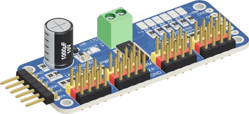
The PCA9685 servo driver is a 16-channel, 12-bit PWM board controlled over I2C at address 0x40, with outputs programmable from 24 Hz to 1526 Hz and a chip that runs from 2.3 V to 5.5 V (NXP PCA9685 datasheet Rev. 4, pp. 1, 25). Wire VCC to the microcontroller's logic voltage, GND, SDA and SCL to the I2C pins, and the servos' own 5 V to 6 V supply to the V+ terminal block, then set the frequency to 50 Hz for servos (Adafruit 16-Channel PWM/Servo Driver guide). Each output sinks 25 mA or sources 10 mA, enough for a servo signal or an LED, never a motor (datasheet, p. 1).
The PCA9685 is NXP's 16-channel LED controller: each output has its own 12-bit PWM generator (4096 steps), all running at one shared frequency set by a prescaler, from about 24 Hz to 1526 Hz, clocked by an internal 25 MHz oscillator (NXP PCA9685 datasheet Rev. 4, pp. 1, 25). Because the chip generates every pulse itself, the microcontroller only writes ON and OFF counts over I2C and is then free; Fast-mode Plus lets the bus run up to 1 MHz (p. 1). Set to 50 Hz, the same outputs make standard hobby-servo pulses.
The breakout board most makers use follows Adafruit's product 815 layout, also sold as the HW-170. It brings out 16 three-pin servo headers (PWM, V+, GND), puts a 220 Ω resistor in series with every PWM line, pulls SDA and SCL up to VCC with 10 kΩ, ties OE low so the outputs are on by default, and feeds the servos from a separate V+ supply through a terminal block with reverse-polarity protection (Adafruit product 815 page; Adafruit guide, Pinouts). VCC powers only the chip and the pull-ups; the servos never take power from it.
The I2C address is 0x40 with the six address pads open; bridging pads adds 1, 2, 4, 8, 16 or 32, covering 0x40 to 0x7F (datasheet, p. 8; Adafruit product 815 page). Two addresses are taken at power-up, the LED All Call address 0x70 and the Software Reset address, which leaves 62 usable addresses, so up to 62 boards and 992 outputs can share one bus (datasheet, p. 7). The bare board measures 62.5 × 25.4 × 3 mm without headers (Adafruit product 815 page).
PCA9685 16-Channel Servo Driver pinout
| Pin | Function | Type |
|---|---|---|
| VPLUS | V+: the servos' supply (6 V max), straight to every output's V+ pin (not protected against reversal: the terminal block is)2.3–5 V | power in |
| VCC | VCC: logic supply, 2.3-5.5 V (also the I2C pull-ups')2.3–5 V | power in |
| SDA | I2C SDA | bidirectional |
| SCL | I2C SCL | bidirectional |
| OE | Digital | input |
| GND | GND | power in |
| VPLUS_CHAIN | V+: the servos' supply (6 V max), straight to every output's V+ pin (not protected against reversal: the terminal block is), the pad to chain the next board2.3–5 V | power in |
| VCC_CHAIN | VCC: logic supply, 2.3-5.5 V (also the I2C pull-ups'), the pad to chain the next board2.3–5 V | power in |
| SDA_CHAIN | I2C SDA | bidirectional |
| SCL_CHAIN | I2C SCL | bidirectional |
| OE_CHAIN | Digital | input |
| GND_CHAIN | GND, the pad to chain the next board | power in |
| TERM_VPLUS | Terminal block V+: the servos' supply, through the reverse-polarity MOSFET2.3–5 V | power in |
| TERM_GND | Terminal block GND2.3–5 V | power in |
| PWM0 | PWM | output |
| VPLUS0 | V+ for servo 0 | passive |
| GND0 | GND for servo 0 | passive |
| PWM1 | PWM | output |
| VPLUS1 | V+ for servo 1 | passive |
| GND1 | GND for servo 1 | passive |
| PWM2 | PWM | output |
| VPLUS2 | V+ for servo 2 | passive |
| GND2 | GND for servo 2 | passive |
| PWM3 | PWM | output |
| VPLUS3 | V+ for servo 3 | passive |
| GND3 | GND for servo 3 | passive |
| PWM4 | PWM | output |
| VPLUS4 | V+ for servo 4 | passive |
| GND4 | GND for servo 4 | passive |
| PWM5 | PWM | output |
| VPLUS5 | V+ for servo 5 | passive |
| GND5 | GND for servo 5 | passive |
| PWM6 | PWM | output |
| VPLUS6 | V+ for servo 6 | passive |
| GND6 | GND for servo 6 | passive |
| PWM7 | PWM | output |
| VPLUS7 | V+ for servo 7 | passive |
| GND7 | GND for servo 7 | passive |
| PWM8 | PWM | output |
| VPLUS8 | V+ for servo 8 | passive |
| GND8 | GND for servo 8 | passive |
| PWM9 | PWM | output |
| VPLUS9 | V+ for servo 9 | passive |
| GND9 | GND for servo 9 | passive |
| PWM10 | PWM | output |
| VPLUS10 | V+ for servo 10 | passive |
| GND10 | GND for servo 10 | passive |
| PWM11 | PWM | output |
| VPLUS11 | V+ for servo 11 | passive |
| GND11 | GND for servo 11 | passive |
| PWM12 | PWM | output |
| VPLUS12 | V+ for servo 12 | passive |
| GND12 | GND for servo 12 | passive |
| PWM13 | PWM | output |
| VPLUS13 | V+ for servo 13 | passive |
| GND13 | GND for servo 13 | passive |
| PWM14 | PWM | output |
| VPLUS14 | V+ for servo 14 | passive |
| GND14 | GND for servo 14 | passive |
| PWM15 | PWM | output |
| VPLUS15 | V+ for servo 15 | passive |
| GND15 | GND for servo 15 | passive |
How to wire the PCA9685 16-Channel Servo Driver
Pin by pin, for the board you have.
| PCA9685 16-Channel Servo Driver | Arduino Uno | Note |
|---|---|---|
| VCC | 5V | |
| GND | GND | |
| SDA | SDA | |
| SCL | SCL |
| PCA9685 16-Channel Servo Driver | ESP32 DevKit V1 | Note |
|---|---|---|
| VCC | 3V3 | |
| GND | GND | |
| SDA | GPIO21 (D21) | |
| SCL | GPIO22 (D22) |
| PCA9685 16-Channel Servo Driver | Raspberry Pi Pico | Note |
|---|---|---|
| VCC | 3V3 | |
| GND | GND | |
| SDA | GP4 | |
| SCL | GP5 |
PCA9685 16-Channel Servo Driver code
Every example here compiles for its board.
// PCA9685 16-Channel Servo Driver on Arduino Uno: wiring and a free simulation at https://www.tinkered.ai/components/pca9685-servo-driver
#include <Arduino.h>
#include <Wire.h>
#include <Adafruit_PWMServoDriver.h>

Adafruit_PWMServoDriver pwm = Adafruit_PWMServoDriver(0x40);

const uint16_t SERVO_MIN_US = 544;
const uint16_t SERVO_MAX_US = 2400;   // 180 degrees

void servoAngle(uint8_t ch, int deg) {
  pwm.writeMicroseconds(ch, map(constrain(deg, 0, 180), 0, 180, SERVO_MIN_US, SERVO_MAX_US));
}

void setup() {
  Serial.begin(115200);
  pwm.begin();
  pwm.setOscillatorFrequency(25000000);
  pwm.setPWMFreq(50);                // servos: 50 Hz
  pwm.setPWM(15, 0, 1024);           // the LED on 15 at 25 % (1024 of 4096)
}

void loop() {
  for (int deg = 0; deg <= 180; deg += 10) {
    servoAngle(0, deg);
    servoAngle(1, 180 - deg);
    delay(100);
  }
  for (int deg = 180; deg >= 0; deg -= 10) {
    servoAngle(0, deg);
    servoAngle(1, 180 - deg);
    delay(100);
  }
}
// PCA9685 16-Channel Servo Driver on ESP32 DevKit V1: wiring and a free simulation at https://www.tinkered.ai/components/pca9685-servo-driver
#include <Arduino.h>
#include <Wire.h>
#include <Adafruit_PWMServoDriver.h>

Adafruit_PWMServoDriver pwm = Adafruit_PWMServoDriver(0x40);

const uint16_t SERVO_MIN_US = 544;
const uint16_t SERVO_MAX_US = 2400;   // 180 degrees

void servoAngle(uint8_t ch, int deg) {
  pwm.writeMicroseconds(ch, map(constrain(deg, 0, 180), 0, 180, SERVO_MIN_US, SERVO_MAX_US));
}

void setup() {
  Serial.begin(115200);
  pwm.begin();
  pwm.setOscillatorFrequency(25000000);
  pwm.setPWMFreq(50);                // servos: 50 Hz
  pwm.setPWM(15, 0, 1024);           // the LED on 15 at 25 % (1024 of 4096)
}

void loop() {
  for (int deg = 0; deg <= 180; deg += 10) {
    servoAngle(0, deg);
    servoAngle(1, 180 - deg);
    delay(100);
  }
  for (int deg = 180; deg >= 0; deg -= 10) {
    servoAngle(0, deg);
    servoAngle(1, 180 - deg);
    delay(100);
  }
}
// PCA9685 16-Channel Servo Driver on Raspberry Pi Pico: wiring and a free simulation at https://www.tinkered.ai/components/pca9685-servo-driver
#include <Arduino.h>
#include <Wire.h>
#include <Adafruit_PWMServoDriver.h>

Adafruit_PWMServoDriver pwm = Adafruit_PWMServoDriver(0x40);

const uint16_t SERVO_MIN_US = 544;
const uint16_t SERVO_MAX_US = 2400;   // 180 degrees

void servoAngle(uint8_t ch, int deg) {
  pwm.writeMicroseconds(ch, map(constrain(deg, 0, 180), 0, 180, SERVO_MIN_US, SERVO_MAX_US));
}

void setup() {
  Serial.begin(115200);
  pwm.begin();
  pwm.setOscillatorFrequency(25000000);
  pwm.setPWMFreq(50);                // servos: 50 Hz
  pwm.setPWM(15, 0, 1024);           // the LED on 15 at 25 % (1024 of 4096)
}

void loop() {
  for (int deg = 0; deg <= 180; deg += 10) {
    servoAngle(0, deg);
    servoAngle(1, 180 - deg);
    delay(100);
  }
  for (int deg = 180; deg >= 0; deg -= 10) {
    servoAngle(0, deg);
    servoAngle(1, 180 - deg);
    delay(100);
  }
}
Before you wire it
- VCC to the microcontroller board's logic supply (3V3 on an ESP32, a Pico, an STM32; 5V on an Uno), GND to its GND, SDA/SCL to its I2C pins (Uno A4/A5, ESP32 GPIO21/22, Pico GP4/GP5, Nucleo D14/D15, NodeMCU D2/D1). No extra pull-ups: the board has 10 kΩ on both.
- Each servo on one output: brown/black wire to GNDn, red to VPLUSn, orange/yellow (signal) to PWMn.
- In code: pwm.begin(), then pwm.setPWMFreq(50) for servos (any frequency 24-1526 Hz for LEDs), then set each output. A servo takes a pulse of about 0.5-2.5 ms: pwm.writeMicroseconds(ch, 544..2400).
- Several boards on one bus: each its own address (bridge pads), each its own Adafruit_PWMServoDriver(0x41) object.
- Name your own constants without the library's names: Adafruit_PWMServoDriver.h #defines PCA9685_I2C_ADDRESS, PCA9685_MODE1, PCA9685_PRESCALE, PCA9685_PRESCALE_MIN/MAX, PCA9685_LED0_ON_L and the other register names, MODE1_*, MODE2_* and FREQUENCY_OSCILLATOR. constexpr uint8_t PCA9685_I2C_ADDRESS = 0x40; becomes constexpr uint8_t 0x40 = 0x40; and fails in the library's header. Use names of your own: SERVO_DRIVER_ADDR, SERVO_DRIVER_OSC_HZ, SERVO_FREQ_HZ.
- No servos powered from VCC, and NO V+ left unpowered with servos on it: they never move.
- No VCC at 5 V on a 3.3 V board: the pull-ups would put 5 V on SDA/SCL.
- No motor, relay or buzzer straight on an output (25 mA max): drive a TB6612, an L298N or a transistor from it.
- No board at 0x70.
- Power VCC from the microcontroller's logic voltage: 3.3 V on an ESP32, ESP8266 or Pico, 5 V on an Uno. The board's SDA/SCL pull-ups go to VCC, and SDA and SCL read high only above 0.7 × VCC (datasheet, p. 38), so VCC must match the board's logic.
- Feed the servos from their own supply on V+, typically 5 V to 6 V (Adafruit guide, Pinouts), on the terminal block so the reverse-polarity protection applies. Join its ground to the microcontroller's GND; on the board they are the same net.
- Size the V+ supply for all the servos moving at once. A USB port or an Arduino's 5 V pin cannot carry several servos; a 5 V adapter rated for a few amps can.
- Call setPWMFreq(50) for analog servos. At 50 Hz one count is 20 ms ÷ 4096, about 4.9 µs, and the prescaler value is round(25 MHz ÷ (4096 × 50)) - 1 = 121 (datasheet, equation 1, p. 25).
- The datasheet gives the internal oscillator as 25 MHz typical (p. 1) with no tolerance, so pulse widths on a given chip can be a little off. Measure a pulse and correct it with setOscillatorFrequency() in Adafruit's library when servo angles must be exact.
- Never give a board the address 0x70: every PCA9685 answers its All Call address at power-up (datasheet, p. 8).
- OE is active low and pulled low on the board; drive it high from a GPIO to switch all 16 outputs off at once (Adafruit guide, Pinouts).
- V+, the servos' supply, takes 5 to 6 V (12 V maximum).
Specifications
- Channels
- 16 outputs, 12-bit (4096-step) PWM eachNXP PCA9685 datasheet Rev. 4, p. 1
- PWM frequency
- 24 Hz to 1526 Hz, one frequency for all outputs; 200 Hz defaultNXP PCA9685 datasheet Rev. 4, pp. 1, 25
- Chip supply (VCC)
- 2.3 V to 5.5 V; I/Os 5.5 V tolerantNXP PCA9685 datasheet Rev. 4, pp. 1, 38
- Output drive
- 25 mA sink, 10 mA source per output at 5 V; 400 mA totalNXP PCA9685 datasheet Rev. 4, pp. 1, 38
- I2C address
- 0x40 default, 0x40 to 0x7F with six address pads; 0x70 reserved (All Call)NXP PCA9685 datasheet Rev. 4, pp. 7, 8
- I2C speed
- Up to 1 MHz (Fast-mode Plus)NXP PCA9685 datasheet Rev. 4, pp. 1, 40
- Oscillator
- 25 MHz internal, or external clock up to 50 MHz on EXTCLKNXP PCA9685 datasheet Rev. 4, p. 1
- Supply current
- 6 mA typ, 10 mA max operating; 2.2 µA typ standbyNXP PCA9685 datasheet Rev. 4, p. 38
- Board features
- 220 Ω series resistor per output, 10 kΩ SDA/SCL pull-ups, reverse polarity protection on the terminal block, power LEDAdafruit product 815 page; Adafruit 16-Channel PWM/Servo Driver guide, Pinouts
- Board size
- 62.5 × 25.4 × 3 mm without headersAdafruit product 815 page
- Supply voltage
- 2.3–5 V
- Maximum supply voltage
- 5.5 V
- Interface
- I2C
- On-board I2C pull-ups
- Yes (10 kΩ)
- Dimensions
- 70.37 × 25.4 × 16.2 mm
- Weight
- 12 g
From the NXP PCA9685 / Adafruit 815 layout (generic HW-170 board)'s datasheet, published by NXP PCA9685 / Adafruit 815 layout (generic HW-170 board).
Common mistakes
Powering the servos from VCC or leaving V+ unpowered
VCC feeds only the chip and the pull-ups. The servos' red wires sit on V+, so without a supply on the terminal block the signals are fine but nothing moves.
Running servos from the microcontroller's 5 V pin
A few servos starting together pull far more current than USB supplies, so the voltage dips and the board resets. Give V+ a separate 5 V to 6 V supply.
Forgetting setPWMFreq(50)
The chip powers up at 200 Hz (datasheet, p. 25). Servos expect a 50 Hz frame, so set the frequency in setup() before writing any pulse.
Driving motors or relays straight from an output
An output sinks 25 mA and sources 10 mA (datasheet, p. 1). That drives a servo signal or an LED, not a DC motor, relay or solenoid; put a driver such as a TB6612FNG, L298N or a MOSFET in between.
VCC at 5 V with a 3.3 V microcontroller
The pull-ups then hold SDA and SCL at 5 V, above a 3.3 V board's pin rating. Power VCC from 3.3 V on 3.3 V boards.
PCA9685 16-Channel Servo Driver questions
Can I use the PCA9685 with an ESP32, Pico or other 3.3 V board?
Yes. Power VCC from 3.3 V: the chip runs from 2.3 V to 5.5 V and its I2C inputs read high above 0.7 × VCC (NXP datasheet, pp. 1, 38), and the board's pull-ups then hold SDA and SCL at 3.3 V. The servos keep their own 5 V to 6 V supply on V+.
How many servos can one PCA9685 control, and how many boards can I chain?
16 servos per board. The six address pads give addresses 0x40 to 0x7F, and with the All Call and Software Reset addresses reserved, 62 boards can share one I2C bus for 992 outputs (NXP datasheet, p. 7; Adafruit product 815 page).
Why do my servos not move with the PCA9685?
The usual cause is no power on V+: VCC only runs the chip. Then check that the I2C address matches (0x40 by default), that setPWMFreq(50) was called, that OE is not pulled high, and that the servo plug is the right way round with the signal wire on PWM.
What PWM frequency should I use for servos and LEDs?
50 Hz for standard servos. For LEDs any frequency from 24 Hz to 1526 Hz works, and higher avoids visible flicker (NXP datasheet, p. 25). All 16 outputs share one frequency, so a board cannot drive servos at 50 Hz and LEDs at 1 kHz at the same time.
What voltage should I put on V+?
Whatever your servos are rated for, typically 5 V to 6 V for SG90 and MG996R-class servos (Adafruit guide, Pinouts). Use the terminal block, which has reverse-polarity protection, and a supply that can deliver every servo's stall current together.
Can the PCA9685 dim LEDs?
Yes, it is an LED controller first: 12-bit PWM per output, sinking up to 25 mA (NXP datasheet, p. 1). The breakout's 220 Ω series resistors (Adafruit product 815 page) let you connect an LED from an output to GND directly.
Build something with the PCA9685 16-Channel Servo Driver
- Build this
Robot arm
Drive five or six servos for a desktop arm from two I2C pins, leaving the rest of the board free.
- Build this
Hexapod or quadruped walker
Coordinate 12 to 18 leg servos with one or two chained boards.
- Build this
Animatronic face
Move eyes, eyelids and jaw servos in sync with sound.
- Build this
Pan-tilt camera mount
Point an ESP32-CAM or a webcam with two servos.
- Build this
16-channel LED dimmer
Fade 16 LEDs or LED drivers smoothly with 4096-step PWM.
This page as plain Markdown, for ChatGPT, Claude or your own agent. /components/pca9685-servo-driver.md