Green LED
A standard 5mm (T-1 3/4) through-hole green LED with a forward voltage near 2.1V that always needs a series current-limiting resistor.

What is the Green LED?
The green LED is a two-terminal indicator diode in the common 5mm (T-1 3/4) through-hole package. It emits green light (typically a gallium phosphide emitter with a peak wavelength around 565nm) when current flows from the anode to the cathode. Like any diode it is polarized, so it only lights when connected the correct way around.
Electrically the part behaves as a diode with a forward voltage of about 2.1V at typical operating currents. Standard 5mm green LEDs are driven at roughly 10 to 20mA. Because the diode's current climbs steeply once the forward voltage is reached, the LED must never be wired directly across a supply. A series resistor is required to set a safe operating current.
It is one of the most common status and power indicators in Arduino and hobby electronics projects, and it is passive from the simulator's point of view (it is driven by the pins and resistor around it rather than being programmed).
Specifications
- Forward voltage
- 2.1 V
- Dimensions
- 5 × 8.6 × 5 mm
Verified from the Tinkered component library.
Circuit requirements
- Always place a series current-limiting resistor in line with the LED. Never connect it directly across a supply rail or straight to a microcontroller pin.
- Size the resistor from R = (Vsupply - 2.1V) / I. For a 5V Arduino pin at about 15mA this gives roughly 200 ohms, so a 220 ohm resistor is a common, safe choice; values in the 150-330 ohm range work for typical brightness.
- Observe polarity: the longer lead is the anode (+) and goes toward the positive side; the shorter lead, on the flattened edge of the package rim, is the cathode (-) and goes toward ground.
- Keep the forward current within the part's rating (about 20mA of continuous DC for a standard 5mm green LED). Running it hotter shortens its life.
- The LED tolerates only a small reverse voltage (on the order of 5V), so avoid reverse-biasing it beyond that.
Board compatibility
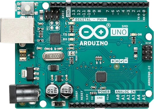
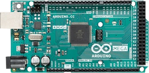
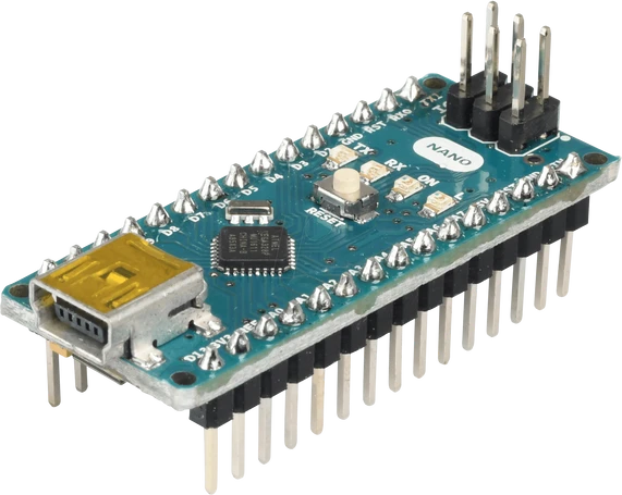
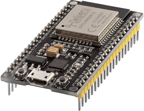
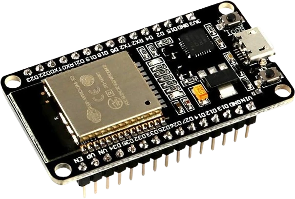
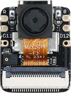
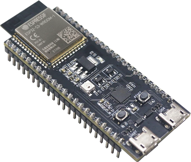
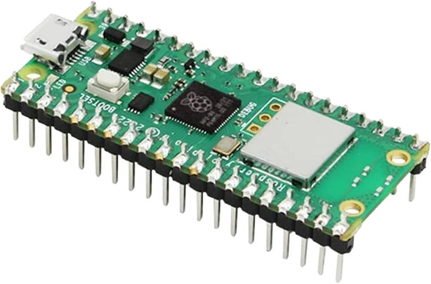
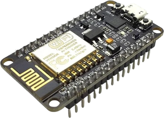
The Green LED connects to any of the microcontrollers supported in Tinkered.
Common Green LED mistakes
Wiring the LED backwards
A reversed LED simply stays dark and gives no other clue. Remember the shorter leg and the flat spot on the rim mark the cathode (-), which connects toward ground; the longer leg is the anode (+).
Leaving out the series resistor
Connecting the LED straight across 5V lets current run away well past its safe level, quickly overheating and destroying the LED and stressing whatever pin drives it. A current-limiting resistor is mandatory, even for a quick test.
Reusing a red LED's resistor value
A green LED's forward voltage (about 2.1V) differs from a red one's (about 1.8V to 2.0V), so recompute the resistor rather than copying a value from another color. The wrong value leaves it dim or over-driven.
Sharing one resistor across several parallel LEDs
Small differences in forward voltage make parallel LEDs on a single resistor draw uneven current, so some glow brighter and run hotter. Give each LED its own series resistor.
Exceeding the microcontroller's current budget
Driving many LEDs directly from one board can blow past the per-pin and total supply current limits. Track the combined draw and add transistors or a driver when it gets large.
More leds & addressable




Build with the Green LED.
Drop the Green LED into a circuit, write firmware, and simulate it in your browser, then deploy to real hardware. All in one editable Tinkered project.