Wi-Fi sensor node to the cloud
Read a temperature, humidity, or light sensor and push readings over Wi-Fi to an MQTT broker, ThingSpeak, or a home dashboard.
A breadboard-friendly ESP32-WROOM-32 development board with dual-core 240 MHz processing, Wi-Fi, and Bluetooth on a 30-pin layout.
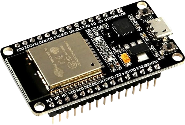
The DOIT ESP32 DevKit V1 is a compact development board built around the Espressif ESP32-WROOM-32 module. That module carries a dual-core Xtensa LX6 processor clocked up to 240 MHz, 4 MB of SPI flash, and 520 KB of on-chip SRAM, with integrated Wi-Fi 802.11 b/g/n and Bluetooth 4.2 (Classic BR/EDR plus BLE) on a single chip. This combination of processing power and wireless connectivity is what makes the ESP32 a default choice for connected projects.
The 30-pin board is designed for prototyping. Its dual-row header spacing drops onto a breadboard, and an onboard USB-to-UART bridge (CP2102 on genuine DOIT boards) plus auto-reset circuitry let you program and monitor over the Micro-USB connector without external hardware. Broken out to the pins are 25 usable GPIO, 15 channels of 12-bit ADC, two DAC outputs, 16 PWM-capable channels, and hardware SPI, I2C, and two UARTs. A built-in LED sits on GPIO2, and BOOT and EN buttons handle flashing and reset.
Makers use the DevKit V1 for IoT sensor nodes, Wi-Fi web servers and home-automation controllers, BLE peripherals and beacons, MQTT clients, and ESP-NOW device-to-device links. It is programmable through the Arduino IDE, Espressif's ESP-IDF, and MicroPython, so the same board suits both beginner sketches and lower-level firmware.
| Pin | Function | Type |
|---|---|---|
VIN VIN | Power | Power in |
GND_L GND | Power | Power in |
IO13 D13 (IO13) | PWM · Digital | Bidirectional (GPIO) |
IO12 D12 (IO12) | PWM · Digital · Strapping selects flash voltage at boot (LOW=3.3V default, HIGH=1.8V can brick board) | Bidirectional (GPIO) |
IO14 D14 (IO14) | PWM · Digital | Bidirectional (GPIO) |
IO27 D27 (IO27) | Digital | Bidirectional (GPIO) |
IO26 D26 (DAC2) | Analog DAC_2 · Digital | Bidirectional (GPIO) |
IO25 D25 (DAC1) | Analog DAC_1 · Digital | Bidirectional (GPIO) |
IO33 D33 (IO33) | Analog ADC1_CH5 · Digital | Bidirectional (GPIO) |
IO32 D32 (IO32) | Analog ADC1_CH4 · Digital | Bidirectional (GPIO) |
IO35 D35 (IO35) | Analog ADC1_CH7 · Digital | Digital input |
IO34 D34 (IO34) | Analog ADC1_CH6 · Digital | Digital input |
VN VN (IO39) | Analog ADC1_CH3 · Digital | Digital input |
VP VP (IO36) | Analog ADC1_CH0 · Digital | Digital input |
EN EN | Digital | Digital input |
3V3 3V3 | Power | Power out |
GND_R GND | Power | Power in |
IO15 D15 (IO15) | Digital · Strapping controls boot debug log on UART0 (HIGH=enabled, LOW=silent) | Bidirectional (GPIO) |
IO2 D2 (LED) | PWM · Digital · Strapping must be LOW or floating at boot — built-in LED pulls it down via R | Bidirectional (GPIO) |
IO4 D4 (IO4) | PWM · Digital | Bidirectional (GPIO) |
RX2 RX2 (IO16) | UART RX · PWM · Digital | Bidirectional (GPIO) |
TX2 TX2 (IO17) | UART TX · PWM · Digital | Bidirectional (GPIO) |
IO5 D5 (CS) | SPI CS · PWM · Digital · Strapping controls SDIO slave timing at boot (default HIGH via internal pull-up) | Bidirectional (GPIO) |
IO18 D18 (SCK) | SPI SCK · Digital | Bidirectional (GPIO) |
IO19 D19 (CIPO) | SPI MISO · Digital | Bidirectional (GPIO) |
IO21 D21 (SDA) | I²C SDA · Digital | Bidirectional (GPIO) |
RX0 RX0 (IO3) | UART RX · Digital | Bidirectional (GPIO) |
TX0 TX0 (IO1) | UART TX · Digital | Bidirectional (GPIO) |
IO22 D22 (SCL) | I²C SCL · Digital | Bidirectional (GPIO) |
IO23 D23 (COPI) | SPI MOSI · Digital | Bidirectional (GPIO) |
Verified from the Tinkered component library · DOIT.
The ESP32 DevKit V1 is fully simulated in Tinkered. Wire it into a circuit, write your firmware, and read real values back with no physical hardware. Test your logic before you touch a breadboard.
Open it in the simulatorUnlike a 5V Arduino, the ESP32's pins are 3.3V. Feeding a 5V sensor output, relay board signal, or 5V pull-up into a GPIO can stress or destroy the pin. Level-shift anything above 3.3V.
These four pins are input-only and have no internal pull resistors. A common surprise is a button on GPIO34 that never reads reliably, or a digitalWrite that silently does nothing. Reserve them for inputs and add external resistors.
The ADC2 block is shared with the Wi-Fi radio. Analog reads on ADC2 pins return errors or garbage once Wi-Fi is connected. Move analog sensors to ADC1 pins for any networked project.
GPIO0, GPIO2, GPIO5, GPIO12, and GPIO15 are sampled at boot to set flash voltage and boot mode. Pulling GPIO12 high can select 1.8V flash and brick booting; a device that holds GPIO0 low can force download mode. Keep these pins free of strong external pulls during reset.
The 30-pin DOIT board is wide. On a standard breadboard it covers the center channel and leaves only one free row per side, or none. Many builders straddle two breadboards or use jumper leads out to a second board.
Read a temperature, humidity, or light sensor and push readings over Wi-Fi to an MQTT broker, ThingSpeak, or a home dashboard.
Host a small web page on the board to switch relays, lights, or fans from any phone on the network, no cloud account required.
Advertise sensor data over Bluetooth Low Energy or act as a BLE beacon for presence detection and phone-to-board control.
Use Espressif's ESP-NOW protocol to send data directly between ESP32 boards without a router, ideal for low-latency remote sensors.
Subscribe and publish over MQTT to tie the board into Home Assistant, Node-RED, or a custom automation pipeline.
Combine buttons and a joystick with the board's Bluetooth stack to build a wireless gamepad or macro pad.
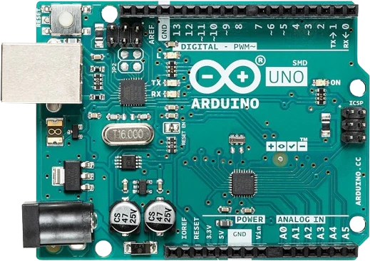
arduino-unoATmega328P · 5V logic
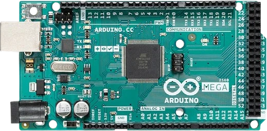
arduino-megaATmega2560 · Expanded I/O
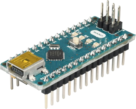
arduino-nano-v3ATmega328P · Compact format
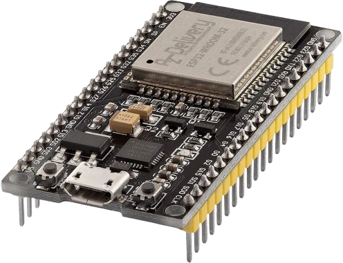
esp32-devkitWi-Fi + Bluetooth
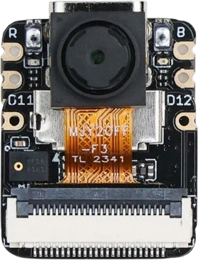
xiao-esp32-s3-senseCompact AI + wireless
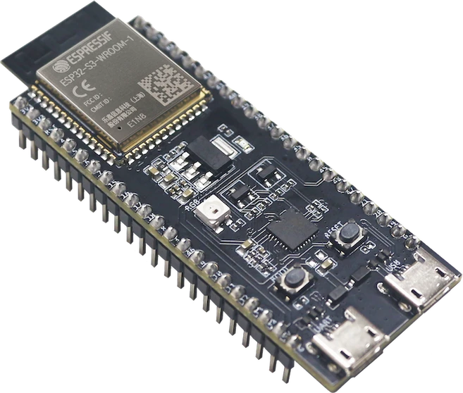
esp32-s3-wroom-freenoveFreenove development board
Drop the ESP32 DevKit V1 into a circuit, write firmware, and simulate it in your browser, then deploy to real hardware. All in one editable Tinkered project.