Wi-Fi camera streamer
Use the onboard camera connector and 2.4 GHz Wi-Fi to serve a live MJPEG video stream or snapshot web page, the classic ESP32-CAM style project with more flash and PSRAM to spare.
Freenove development board built on the ESP32-S3-WROOM-1 module: a dual-core Wi-Fi and Bluetooth LE MCU board with onboard camera connector, addressable RGB LED, and native USB-C.
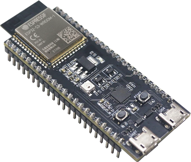
The Freenove ESP32-S3-WROOM is a development board built around Espressif's ESP32-S3-WROOM-1 module. At its core is a dual-core Xtensa LX7 32-bit processor that runs at up to 240 MHz, with integrated 2.4 GHz Wi-Fi (802.11 b/g/n) and Bluetooth 5 (LE). The N16R8 module pairs 16 MB of flash with 8 MB of octal PSRAM and 512 KB of on-chip SRAM, so it has far more headroom than a classic 8-bit Arduino.
Freenove breaks out 36 GPIO across two header rows and adds maker-friendly hardware: a USB-C port for power, programming, and native USB-OTG; an onboard camera connector (OV2640-class); a microSD card slot; and a WS2812 addressable RGB LED on IO48. Nearly every pin is multi-function, exposing 12-bit SAR ADC inputs (20 channels split across ADC1 and ADC2), LEDC PWM, and default hardware I2C, SPI, and UART.
Makers reach for this board for camera streaming and computer-vision demos, Wi-Fi and BLE IoT nodes, and USB HID gadgets. It programs from the Arduino IDE, ESP-IDF, or MicroPython, and the S3's SIMD instruction extensions plus hardware floating-point unit make it capable of lightweight on-device audio and ML workloads.
| Pin | Function | Type |
|---|---|---|
3V3 3V3 | Power | Power out |
EN EN (RST) | Digital chip enable / active-low reset | Digital input |
IO4 IO4 (A3) | Analog ADC1_CH3 · Digital · PWM | Bidirectional (GPIO) |
IO5 IO5 (A4) | Analog ADC1_CH4 · Digital · PWM | Bidirectional (GPIO) |
IO6 IO6 (A5) | Analog ADC1_CH5 · Digital · PWM | Bidirectional (GPIO) |
IO7 IO7 (A6) | Analog ADC1_CH6 · Digital · PWM | Bidirectional (GPIO) |
IO15 IO15 (A4/CH4) | Analog ADC2_CH4 · Digital · PWM | Bidirectional (GPIO) |
IO16 IO16 (A5/CH5) | Analog ADC2_CH5 · Digital · PWM | Bidirectional (GPIO) |
IO17 IO17 (A6/CH6) | Analog ADC2_CH6 · Digital · PWM | Bidirectional (GPIO) |
IO18 IO18 (A7/CH7) | Analog ADC2_CH7 · Digital · PWM | Bidirectional (GPIO) |
IO8 IO8 (SDA) | Analog ADC1_CH7 · Digital · PWM · I²C SDA (default) | Bidirectional (GPIO) |
IO3 IO3 | Analog ADC1_CH2 · Digital · PWM · Strapping JTAG source select at boot (leave floating for normal boot) | Bidirectional (GPIO) |
IO46 IO46 (LOG) | Digital · PWM · Strapping ROM boot-log enable (HIGH=enabled); keep default at boot | Bidirectional (GPIO) |
IO9 IO9 (SCL) | Analog ADC1_CH8 · Digital · PWM · I²C SCL (default) | Bidirectional (GPIO) |
IO10 IO10 (SS) | Analog ADC1_CH9 · Digital · PWM · SPI CS (default FSPI) | Bidirectional (GPIO) |
IO11 IO11 (MOSI) | Analog ADC2_CH0 · Digital · PWM · SPI MOSI (default FSPI) | Bidirectional (GPIO) |
IO12 IO12 (SCK) | Analog ADC2_CH1 · Digital · PWM · SPI SCK (default FSPI) | Bidirectional (GPIO) |
IO13 IO13 (MISO) | Analog ADC2_CH2 · Digital · PWM · SPI MISO (default FSPI) | Bidirectional (GPIO) |
IO14 IO14 | Analog ADC2_CH3 · Digital · PWM | Bidirectional (GPIO) |
5V 5V (VBUS) | Power | Power in |
IO43 IO43 (TX) | UART TX (U0TXD) · Digital · PWM | Bidirectional (GPIO) |
IO44 IO44 (RX) | UART RX (U0RXD) · Digital · PWM | Bidirectional (GPIO) |
IO1 IO1 (A0) | Analog ADC1_CH0 · Digital · PWM | Bidirectional (GPIO) |
IO2 IO2 (LED/A1) | Analog ADC1_CH1 · Digital · PWM | Bidirectional (GPIO) |
IO42 IO42 (MTMS) | Digital · PWM | Bidirectional (GPIO) |
IO41 IO41 (MTDI) | Digital · PWM | Bidirectional (GPIO) |
IO40 IO40 (MTDO) | Digital · PWM | Bidirectional (GPIO) |
IO39 IO39 (MTCK) | Digital · PWM | Bidirectional (GPIO) |
IO38 IO38 | Digital · PWM | Bidirectional (GPIO) |
IO37 IO37 (PSRAM*) | Digital reserved — octal PSRAM on N16R8, do not use | Bidirectional (GPIO) |
IO36 IO36 (PSRAM*) | Digital reserved — octal PSRAM on N16R8, do not use | Bidirectional (GPIO) |
IO35 IO35 (PSRAM*) | Digital reserved — octal PSRAM on N16R8, do not use | Bidirectional (GPIO) |
IO0 IO0 (BOOT) | Digital · PWM · Strapping BOOT button — hold LOW at reset to enter download mode | Bidirectional (GPIO) |
IO45 IO45 (VSPI) | Digital · PWM · Strapping selects flash/PSRAM voltage at boot (default LOW) | Bidirectional (GPIO) |
IO48 IO48 (RGB) | Digital · PWM · 1-Wire onboard WS2812 RGB LED | Bidirectional (GPIO) |
IO47 IO47 | Digital · PWM | Bidirectional (GPIO) |
IO21 IO21 | Digital · PWM | Bidirectional (GPIO) |
IO20 IO20 (D+) | Analog ADC2_CH9 · Digital · PWM · Digital USB D+ | Bidirectional (GPIO) |
IO19 IO19 (D-) | Analog ADC2_CH8 · Digital · PWM · Digital USB D- | Bidirectional (GPIO) |
GND GND | Power | Power in |
Verified from the Tinkered component library · Freenove.
The ESP32-S3 runs on 3.3V logic and its pins are not 5V tolerant. Wiring a 5V output straight into a GPIO can permanently damage the input. Use a logic level shifter or a voltage divider for 5V signals.
ADC2 is used internally by the Wi-Fi radio, so analogRead on an ADC2 channel returns garbage or fails once Wi-Fi is initialized. Move analog sensors to ADC1 pins (IO1-IO10) for any project that also uses the network.
On the N16R8 module, IO35, IO36, and IO37 are dedicated to the octal PSRAM interface. Connecting anything to them causes crashes or boot loops. Treat them as unavailable.
If auto-reset uploading fails, the board never enters the bootloader. Hold the BOOT button (IO0 LOW) while tapping reset, then release, to force download mode before flashing.
The 3V3 pin is a regulator output, not an input, and powering the board from USB and the 5V pin at the same time can create supply conflicts. Pick one power source and only draw 3.3V from the 3V3 pin.
Use the onboard camera connector and 2.4 GHz Wi-Fi to serve a live MJPEG video stream or snapshot web page, the classic ESP32-CAM style project with more flash and PSRAM to spare.
Read temperature, humidity, or light sensors over I2C and publish readings to a built-in web server or an MQTT broker for a home dashboard.
Advertise as a BLE beacon, heart-rate monitor, or wireless gamepad using the integrated Bluetooth 5 (LE) radio.
Drive the onboard WS2812 on IO48 plus external LED strips for status indicators, ambient lighting, or reactive effects.
Take advantage of native USB-OTG on the USB-C port to emulate a keyboard, mouse, or MIDI device without an extra USB chip.
Combine the SD card slot with the ADC and Wi-Fi to log sensor data locally and sync or download it over the network.
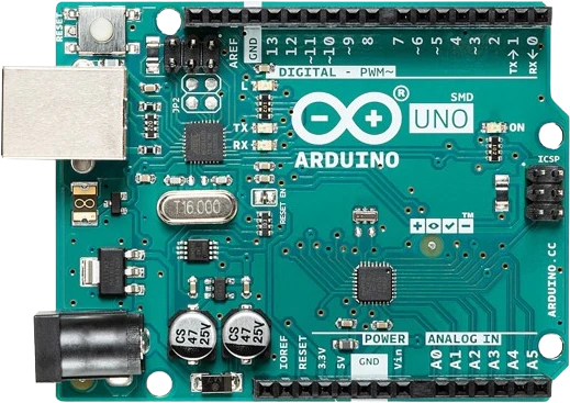
arduino-unoATmega328P · 5V logic
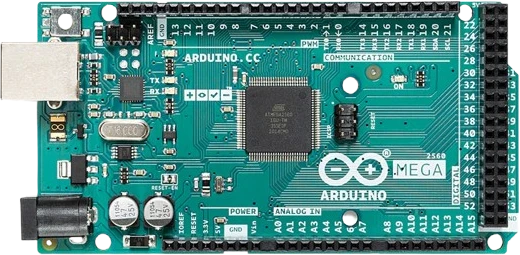
arduino-megaATmega2560 · Expanded I/O
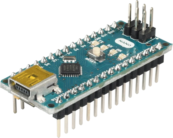
arduino-nano-v3ATmega328P · Compact format
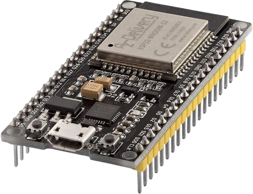
esp32-devkitWi-Fi + Bluetooth
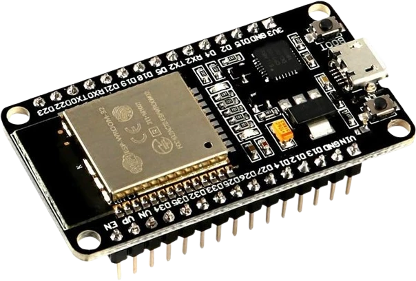
esp32-devkit-v1DOIT · 30-pin
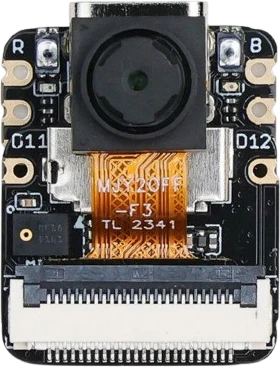
xiao-esp32-s3-senseCompact AI + wireless
Drop the ESP32-S3-WROOM into a circuit, write firmware, and simulate it in your browser, then deploy to real hardware. All in one editable Tinkered project.