Permanent breadboard and perfboard builds
The DIP-style pin layout lets the Nano stay soldered into a finished project, making it a natural upgrade from an Uno prototype to a compact, standalone board.
A breadboard-friendly ATmega328P board that packs an Uno's capability into a compact 30-pin format.
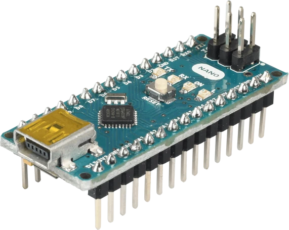
The Arduino Nano V3 is a compact microcontroller board built around the ATmega328P, the same 8-bit AVR chip used in the Arduino Uno. It runs at 16 MHz with 5V logic and carries 32 KB of flash, 2 KB of SRAM, and 1 KB of EEPROM. The board measures just 43.2 x 17.8 mm and presents its pins as two rows of male headers, so it seats directly across the center channel of a standard breadboard for solderless prototyping.
Despite its size, the Nano exposes 22 general-purpose I/O pins, 8 analog inputs (A0 through A7, two more channels than the Uno) at 10-bit resolution, and 6 PWM outputs. Hardware UART, I2C, and SPI peripherals are all available on the header. An onboard FTDI FT232RL bridges USB to serial over a Mini-B connector, handling both sketch uploads and the serial monitor without any external programmer.
Because it shares the ATmega328P core, the Nano runs the same sketches, libraries, and toolchain as the Uno with no code changes. Makers reach for it when a project needs the Uno feature set in a smaller footprint: permanent breadboard or perfboard builds, small robots, wearables, and embedded sensor nodes where the Uno's larger board would not fit.
| Pin | Function | Type |
|---|---|---|
D12 D12 (MISO) | SPI MISO · Digital | Bidirectional (GPIO) |
D11 D11 (MOSI) | SPI MOSI · PWM · Digital | Bidirectional (GPIO) |
D10 D10 (SS) | SPI CS · PWM · Digital | Bidirectional (GPIO) |
D9 D9 | PWM · Digital | Bidirectional (GPIO) |
D8 D8 | Digital | Bidirectional (GPIO) |
D7 D7 | Digital | Bidirectional (GPIO) |
D6 D6 | PWM · Digital | Bidirectional (GPIO) |
D5 D5 | PWM · Digital | Bidirectional (GPIO) |
D4 D4 | Digital | Bidirectional (GPIO) |
D3 D3 | PWM · Digital | Bidirectional (GPIO) |
D2 D2 | Digital | Bidirectional (GPIO) |
GND_R GND | Power | Power in |
RST_R RST | Digital | Digital input |
D0 D0 (RX) | UART RX · Digital | Bidirectional (GPIO) |
D1 D1 (TX) | UART TX · Digital | Bidirectional (GPIO) |
D13 D13 (SCK, LED) | SPI SCK · Digital | Bidirectional (GPIO) |
3V3 3V3 | Power | Power out |
AREF AREF | Analog | Digital input |
A0 A0 | Analog ADC0 · Digital | Bidirectional (GPIO) |
A1 A1 | Analog ADC1 · Digital | Bidirectional (GPIO) |
A2 A2 | Analog ADC2 · Digital | Bidirectional (GPIO) |
A3 A3 | Analog ADC3 · Digital | Bidirectional (GPIO) |
A4 A4 (SDA) | Analog ADC4 · I²C SDA · Digital | Bidirectional (GPIO) |
A5 A5 (SCL) | Analog ADC5 · I²C SCL · Digital | Bidirectional (GPIO) |
A6 A6 | Analog ADC6 | Digital input |
A7 A7 | Analog ADC7 | Digital input |
5V 5V | Power | Power out |
RST_L RST | Digital | Digital input |
GND_L GND | Power | Power in |
VIN VIN | Power | Power in |
Verified from the Tinkered component library · Arduino.
The Arduino Nano V3 is fully simulated in Tinkered. Wire it into a circuit, write your firmware, and read real values back with no physical hardware. Test your logic before you touch a breadboard.
Open it in the simulatorUnlike A0 through A5, the A6 and A7 pins connect only to the ADC. digitalRead, digitalWrite, and pinMode do not work on them. Use them for analog sensors, and keep any button or LED on the other pins.
The 5V pin sits after the regulator, so applying 7-12V there bypasses regulation and can destroy the ATmega328P and connected devices. Unregulated input up to 12V must go to VIN instead.
Many Nano boards ship with the older bootloader. If uploads fail with a sync or timeout error, switch the IDE to the 'ATmega328P (Old Bootloader)' processor option before troubleshooting anything else.
Genuine Nanos use the FTDI FT232RL, while many clones use a CH340 chip. If the board never enumerates as a serial port, install the matching FTDI or CH340 driver for your operating system.
The 3V3 rail comes from the FTDI chip, not a dedicated regulator, and delivers only tens of milliamps. Powering a display or radio module from it can brown out the USB link and cause resets.
The DIP-style pin layout lets the Nano stay soldered into a finished project, making it a natural upgrade from an Uno prototype to a compact, standalone board.
Its light 7 g weight and full complement of PWM and digital pins drive motor controllers, IR sensors, and servos in tabletop robots where board size matters.
Hardware I2C on A4 (SDA) and A5 (SCL) plus 8 analog inputs make it easy to read temperature, humidity, and light sensors and log the data over the USB serial link.
The small footprint fits inside enclosures too tight for an Uno, powering LED effects, counters, and pocket instruments from a battery on VIN.
A single PWM-capable data pin drives strips of individually addressable LEDs, with the extra analog inputs free for potentiometers or sound sensors that set the animation.
Digital outputs switch relay modules for lights and appliances, while the compact board tucks neatly into a project box alongside the relays.
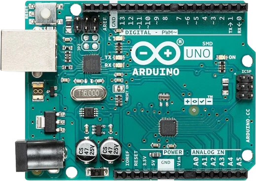
arduino-unoATmega328P · 5V logic
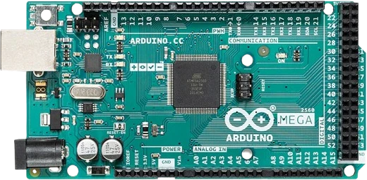
arduino-megaATmega2560 · Expanded I/O
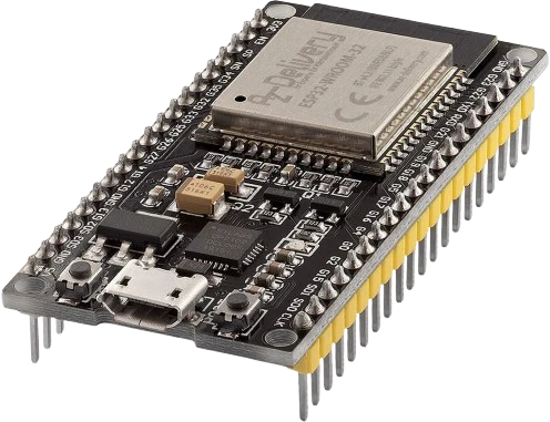
esp32-devkitWi-Fi + Bluetooth
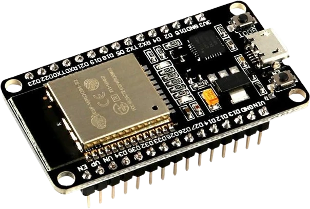
esp32-devkit-v1DOIT · 30-pin
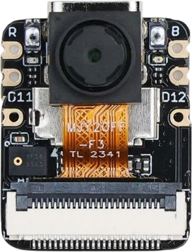
xiao-esp32-s3-senseCompact AI + wireless
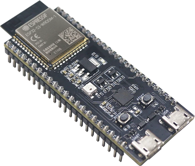
esp32-s3-wroom-freenoveFreenove development board
Drop the Arduino Nano V3 into a circuit, write firmware, and simulate it in your browser, then deploy to real hardware. All in one editable Tinkered project.