Wi-Fi weather and environment station
Read a BME280 or DHT sensor over I2C and publish temperature, humidity, and pressure to a web dashboard or Home Assistant using the ESP32's built-in Wi-Fi.
A Wi-Fi and Bluetooth development board built around the Espressif ESP32-WROOM-32 module, with a dual-core 240 MHz processor and 3.3V GPIO.
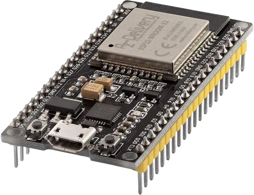
The ESP32 NodeMCU-32S is a development board that breaks out the Espressif ESP32-WROOM-32 module onto a breadboard-friendly form factor. The WROOM-32 module carries a dual-core Xtensa LX6 processor running at up to 240 MHz, 520 KB of on-chip SRAM, and 4 MB of external flash, giving it far more headroom than an 8-bit Arduino for networked and compute-heavy sketches.
Its defining feature is integrated 2.4 GHz Wi-Fi (802.11 b/g/n) plus Bluetooth (Classic BR/EDR and BLE) on the same chip, so a single board can host a web server, publish MQTT telemetry, or act as a BLE peripheral without add-on radios. The board also exposes a wide peripheral set: 18 ADC channels at 12-bit resolution, two 8-bit DAC outputs (IO25 and IO26), hardware I2C, SPI, and UART, plus capacitive touch and 16 independent PWM-capable channels.
Makers program it through the Arduino IDE (via the ESP32 board package), PlatformIO, or ESP-IDF, and power it over the onboard USB-to-UART bridge. It is a common choice for IoT sensor nodes, smart-home controllers, and any project that needs wireless connectivity, more memory, or faster processing than a classic Arduino provides.
| Pin | Function | Type |
|---|---|---|
3V3 3V3 | Power | Power out |
EN EN | Digital | Digital input |
VP SVP (IO36) | Analog ADC1_CH0 · Digital | Digital input |
VN SVN (IO39) | Analog ADC1_CH3 · Digital | Digital input |
IO34 IO34 | Analog ADC1_CH6 · Digital | Digital input |
IO35 IO35 | Analog ADC1_CH7 · Digital | Digital input |
IO32 IO32 | Analog ADC1_CH4 · PWM · Digital | Bidirectional (GPIO) |
IO33 IO33 | Analog ADC1_CH5 · PWM · Digital | Bidirectional (GPIO) |
IO25 IO25 (DAC1) | Analog DAC_1 · PWM · Digital | Bidirectional (GPIO) |
IO26 IO26 (DAC2) | Analog DAC_2 · PWM · Digital | Bidirectional (GPIO) |
IO27 IO27 | PWM · Digital | Bidirectional (GPIO) |
IO14 IO14 | PWM · Digital | Bidirectional (GPIO) |
IO12 IO12 | PWM · Digital · Strapping selects flash voltage at boot (LOW=3.3V default, HIGH=1.8V can brick board) | Bidirectional (GPIO) |
GND_L GND | Power | Power in |
IO13 IO13 | PWM · Digital | Bidirectional (GPIO) |
SD2 SD2 (IO9) | Digital | Bidirectional (GPIO) |
SD3 SD3 (IO10) | Digital | Bidirectional (GPIO) |
CMD CMD (IO11) | Digital | Bidirectional (GPIO) |
VIN VIN (5V) | Power | Power in |
GND_R GND | Power | Power in |
IO23 IO23 (MOSI) | SPI MOSI · Digital | Bidirectional (GPIO) |
IO22 IO22 (SCL) | I²C SCL · Digital | Bidirectional (GPIO) |
TX TX (IO1) | UART TX · Digital | Bidirectional (GPIO) |
RX RX (IO3) | UART RX · Digital | Bidirectional (GPIO) |
IO21 IO21 (SDA) | I²C SDA · Digital | Bidirectional (GPIO) |
GND_RB GND | Power | Power in |
IO19 IO19 (MISO) | SPI MISO · Digital | Bidirectional (GPIO) |
IO18 IO18 (SCK) | SPI SCK · Digital | Bidirectional (GPIO) |
IO5 IO5 | PWM · Digital · Strapping controls SDIO slave timing at boot (default HIGH via internal pull-up) | Bidirectional (GPIO) |
IO17 IO17 | PWM · Digital | Bidirectional (GPIO) |
IO16 IO16 | PWM · Digital | Bidirectional (GPIO) |
IO4 IO4 | PWM · Digital | Bidirectional (GPIO) |
IO0 IO0 | Digital · Strapping must be HIGH at reset (LOW = bootloader / flashing mode) | Bidirectional (GPIO) |
IO2 IO2 (LED) | Digital · Strapping must be LOW or floating at boot — built-in LED pulls it down via R | Bidirectional (GPIO) |
IO15 IO15 | Digital · Strapping controls boot debug log on UART0 (HIGH=enabled, LOW=silent) | Bidirectional (GPIO) |
SD1 SD1 (IO8) | Digital | Bidirectional (GPIO) |
SD0 SD0 (IO7) | Digital | Bidirectional (GPIO) |
CLK CLK (IO6) | Digital | Bidirectional (GPIO) |
Verified from the Tinkered component library · Espressif.
The ESP32 NodeMCU-32S is fully simulated in Tinkered. Wire it into a circuit, write your firmware, and read real values back with no physical hardware. Test your logic before you touch a breadboard.
Open it in the simulatorThe ESP32 is a 3.3V part and its inputs are not 5V tolerant. Feeding a 5V sensor output or 5V serial line into a pin can permanently damage it. Use a level shifter or a resistor divider on any 5V signal.
IO34, IO35, IO36, and IO39 can only read signals. Calling pinMode(OUTPUT) or digitalWrite on them does nothing. Reserve them for buttons, analog sensors, or other read-only inputs and remember they need external pull resistors.
Analog reads on ADC2-mapped pins return garbage once the Wi-Fi radio is enabled because they share the same hardware. If analogRead values go wrong the moment you connect to a network, move the sensor to an ADC1 pin such as IO32-IO35.
IO0, IO2, IO5, IO12, and IO15 are sampled at reset to set boot mode. Pulling IO0 low forces flash mode, and pulling IO12 high can switch the flash to 1.8V and brick the board. Avoid strong external pull-ups or loads on these pins during power-up.
IO6-IO11 (labeled CLK, SD0-SD3, and CMD) connect to the onboard SPI flash. Using them for your own signals crashes the board. Stick to the other exposed pins for wiring.
Read a BME280 or DHT sensor over I2C and publish temperature, humidity, and pressure to a web dashboard or Home Assistant using the ESP32's built-in Wi-Fi.
Sample analog or digital sensors and push readings to an MQTT broker, using deep sleep between reports to stretch battery life for a remote node.
Use the Bluetooth Low Energy radio to advertise sensor data or expose a GATT service that a phone app can connect to, no extra radio module required.
Host a small web server on the board so you can toggle a relay from any browser on the network, turning lamps or appliances into a DIY smart switch.
Link several ESP32 boards with ESP-NOW to relay readings between rooms without a router, useful for whole-home monitoring.
Pair the board's fast dual-core processor and Wi-Fi to stream data, serve a live status page, or bridge serial devices onto the network.
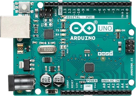
arduino-unoATmega328P · 5V logic
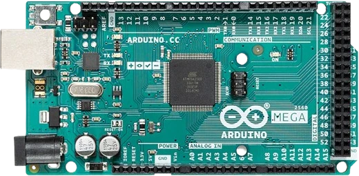
arduino-megaATmega2560 · Expanded I/O
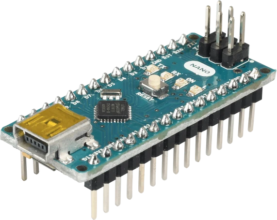
arduino-nano-v3ATmega328P · Compact format
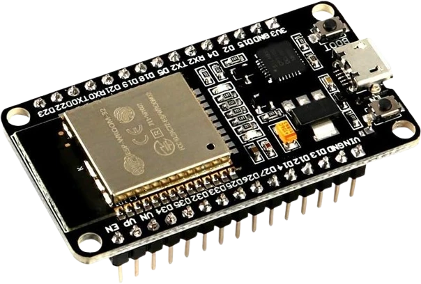
esp32-devkit-v1DOIT · 30-pin
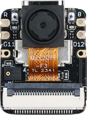
xiao-esp32-s3-senseCompact AI + wireless
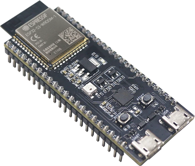
esp32-s3-wroom-freenoveFreenove development board
Drop the ESP32 NodeMCU-32S into a circuit, write firmware, and simulate it in your browser, then deploy to real hardware. All in one editable Tinkered project.