Wi-Fi environmental sensor
Read a temperature, humidity, or air-quality sensor over I2C and push readings to a cloud dashboard or MQTT broker over the onboard Wi-Fi.
RP2040-based microcontroller board with onboard 2.4 GHz Wi-Fi and Bluetooth, built for connected 3.3V projects.
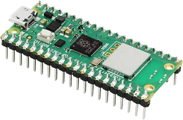
The Raspberry Pi Pico W is a low-cost microcontroller board built around Raspberry Pi's RP2040 chip, a dual-core Arm Cortex-M0+ running at up to 133 MHz with 264 KB of on-chip SRAM and 2 MB of external QSPI flash. It keeps the same 40-pin form factor and pinout as the original Pico while adding wireless connectivity.
Wireless is provided by an Infineon CYW43439 module linked to the RP2040 over SPI. It supports 2.4 GHz IEEE 802.11 b/g/n Wi-Fi and Bluetooth 5.2 (both Classic and LE, enabled through firmware), using an on-board antenna licensed from ABRACON (formerly ProAnt). One quirk to know: the board's user LED is wired to the CYW43439's WL_GPIO0 line rather than to an RP2040 pin, so the wireless driver must be initialized to blink it.
The board exposes 26 multifunction GPIO at 3.3V logic, with 3 analog inputs (12-bit ADC), 16 PWM channels, and 2 each of SPI, I2C, and UART, plus the RP2040's Programmable I/O (PIO) blocks for custom interfaces. Makers program it in C/C++ with the Pico SDK or in MicroPython, and it is powered and flashed over its micro-USB connector, which makes it a popular choice for Wi-Fi sensors, web-controlled hardware, and battery-powered IoT nodes.
| Pin | Function | Type |
|---|---|---|
GP0 GP0 | Digital · PWM · SPI SPI0 RX · UART UART0 TX · I²C I2C0 SDA | Bidirectional (GPIO) |
GP1 GP1 | Digital · PWM · SPI SPI0 CSn · UART UART0 RX · I²C I2C0 SCL | Bidirectional (GPIO) |
GND_3 GND | Power | Power in |
GP2 GP2 | Digital · PWM · SPI SPI0 SCK · UART UART0 CTS · I²C I2C1 SDA | Bidirectional (GPIO) |
GP3 GP3 | Digital · PWM · SPI SPI0 TX · UART UART0 RTS · I²C I2C1 SCL | Bidirectional (GPIO) |
GP4 GP4 | Digital · PWM · SPI SPI0 RX · UART UART1 TX · I²C I2C0 SDA | Bidirectional (GPIO) |
GP5 GP5 | Digital · PWM · SPI SPI0 CSn · UART UART1 RX · I²C I2C0 SCL | Bidirectional (GPIO) |
GND_8 GND | Power | Power in |
GP6 GP6 | Digital · PWM · SPI SPI0 SCK · UART UART1 CTS · I²C I2C1 SDA | Bidirectional (GPIO) |
GP7 GP7 | Digital · PWM · SPI SPI0 TX · UART UART1 RTS · I²C I2C1 SCL | Bidirectional (GPIO) |
GP8 GP8 | Digital · PWM · SPI SPI1 RX · UART UART1 TX · I²C I2C0 SDA | Bidirectional (GPIO) |
GP9 GP9 | Digital · PWM · SPI SPI1 CSn · UART UART1 RX · I²C I2C0 SCL | Bidirectional (GPIO) |
GND_13 GND | Power | Power in |
GP10 GP10 | Digital · PWM · SPI SPI1 SCK · UART UART1 CTS · I²C I2C1 SDA | Bidirectional (GPIO) |
GP11 GP11 | Digital · PWM · SPI SPI1 TX · UART UART1 RTS · I²C I2C1 SCL | Bidirectional (GPIO) |
GP12 GP12 | Digital · PWM · SPI SPI1 RX · UART UART0 TX · I²C I2C0 SDA | Bidirectional (GPIO) |
GP13 GP13 | Digital · PWM · SPI SPI1 CSn · UART UART0 RX · I²C I2C0 SCL | Bidirectional (GPIO) |
GND_18 GND | Power | Power in |
GP14 GP14 | Digital · PWM · SPI SPI1 SCK · UART UART0 CTS · I²C I2C1 SDA | Bidirectional (GPIO) |
GP15 GP15 | Digital · PWM · SPI SPI1 TX · UART UART0 RTS · I²C I2C1 SCL | Bidirectional (GPIO) |
VBUS VBUS | Power | Power in |
VSYS VSYS | Power | Power in |
GND_38 GND | Power | Power in |
3V3_EN 3V3_EN | Digital | Digital input |
3V3 3V3 | Power | Power out |
ADC_VREF ADC_VREF | Analog ADC reference | Digital input |
GP28 GP28 / ADC2 | Analog ADC2 · Digital · PWM · SPI SPI1 RX · UART UART0 TX · I²C I2C0 SDA | Bidirectional (GPIO) |
GND_33 GND / AGND | Power | Power in |
GP27 GP27 / ADC1 | Analog ADC1 · Digital · PWM · SPI SPI1 TX · UART UART1 RTS · I²C I2C1 SCL | Bidirectional (GPIO) |
GP26 GP26 / ADC0 | Analog ADC0 · Digital · PWM · SPI SPI1 SCK · UART UART1 CTS · I²C I2C1 SDA | Bidirectional (GPIO) |
RUN RUN | Digital | Digital input |
GP22 GP22 | Digital · PWM · SPI SPI0 SCK · UART UART1 CTS · I²C I2C1 SDA | Bidirectional (GPIO) |
GND_28 GND | Power | Power in |
GP21 GP21 | Digital · PWM · SPI SPI0 CSn · UART UART1 RX · I²C I2C0 SCL | Bidirectional (GPIO) |
GP20 GP20 | Digital · PWM · SPI SPI0 RX · UART UART1 TX · I²C I2C0 SDA | Bidirectional (GPIO) |
GP19 GP19 | Digital · PWM · SPI SPI0 TX · UART UART0 RTS · I²C I2C1 SCL | Bidirectional (GPIO) |
GP18 GP18 | Digital · PWM · SPI SPI0 SCK · UART UART0 CTS · I²C I2C1 SDA | Bidirectional (GPIO) |
GND_23 GND | Power | Power in |
GP17 GP17 | Digital · PWM · SPI SPI0 CSn · UART UART0 RX · I²C I2C0 SCL | Bidirectional (GPIO) |
GP16 GP16 | Digital · PWM · SPI SPI0 RX · UART UART0 TX · I²C I2C0 SDA | Bidirectional (GPIO) |
Verified from the Tinkered component library · Raspberry Pi.
On the original Pico the onboard LED is GP25, but on the Pico W that pin is used by the wireless chip and the LED moved to the CYW43439's WL_GPIO0. Code that toggles GP25 does nothing; you must initialize the wireless driver and use the cyw43 'LED' pin instead.
The RP2040 runs at 3.3V logic and its pins are not 5V tolerant. Wiring a 5V sensor output, another 5V board, or a 5V I2C bus straight to a GP pin can damage it. Use a level shifter or voltage divider.
GPIO used to interface the CYW43439 (and VSYS voltage sensing) are consumed internally on the Pico W and are not free general-purpose pins on the header. Do not plan a design that reuses them for your own signals.
In MicroPython, failing to set the wireless country (for example rp2.country('US')) or leaving default region settings can cause the board to fail to connect or scan properly. Configure the region before joining a network.
Injecting external 5V into VBUS while the board is also plugged into a computer's USB can create conflicting supplies. For battery or external power, feed VSYS through a diode rather than driving VBUS.
Read a temperature, humidity, or air-quality sensor over I2C and push readings to a cloud dashboard or MQTT broker over the onboard Wi-Fi.
Run a small MicroPython or C web server on the Pico W so a phone or laptop can switch relays, LEDs, or motors from a web page on the local network.
Publish sensor data and subscribe to commands over MQTT to tie the board into Home Assistant or another smart-home hub.
Use the CYW43439's Bluetooth 5.2 LE support to broadcast sensor values or act as a BLE peripheral for a phone app.
Sync time from an NTP server over Wi-Fi and show it on an OLED or LED matrix, with no external RTC required.
Sample analog inputs on the 12-bit ADC and stream them to a service like Adafruit IO or ThingSpeak for remote graphing and alerts.
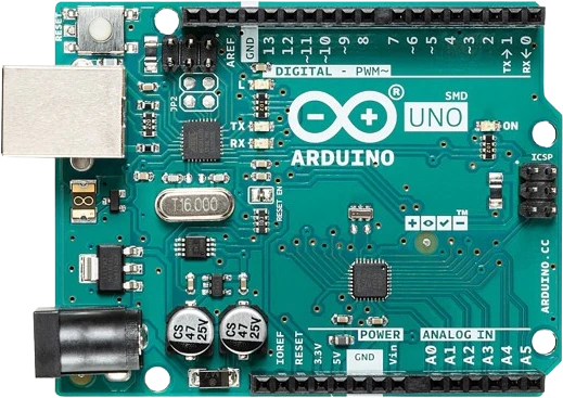
arduino-unoATmega328P · 5V logic
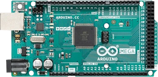
arduino-megaATmega2560 · Expanded I/O
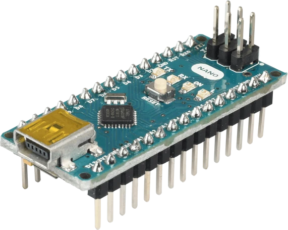
arduino-nano-v3ATmega328P · Compact format
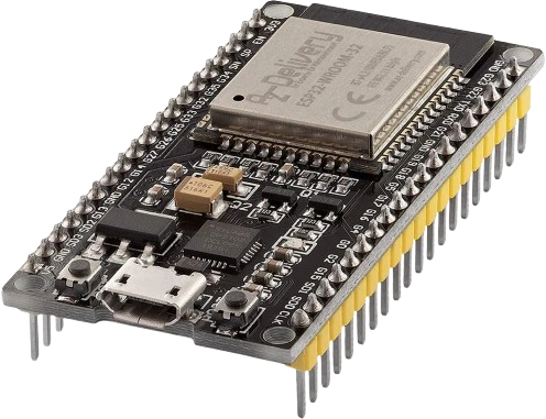
esp32-devkitWi-Fi + Bluetooth
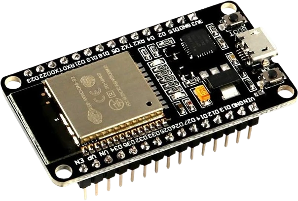
esp32-devkit-v1DOIT · 30-pin
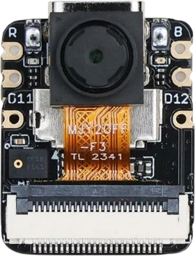
xiao-esp32-s3-senseCompact AI + wireless
Drop the Raspberry Pi Pico W into a circuit, write firmware, and simulate it in your browser, then deploy to real hardware. All in one editable Tinkered project.