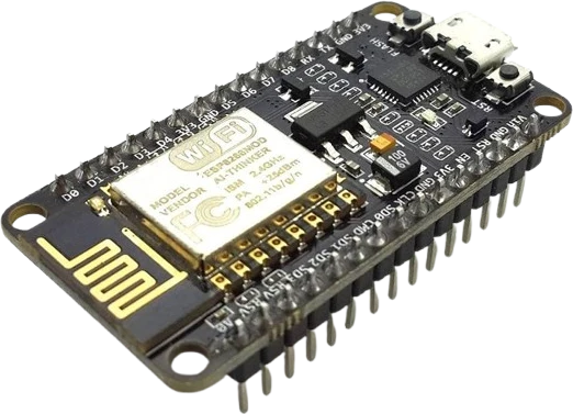
Sensor readout panel
Display live temperature, humidity, or distance from a sensor like a DHT22 or HC-SR04 on line 1 and 2, refreshed in the loop.
A 16x2 character display driven over I²C, so a full HD44780 text screen runs on just two signal wires instead of the usual six or more parallel data lines.
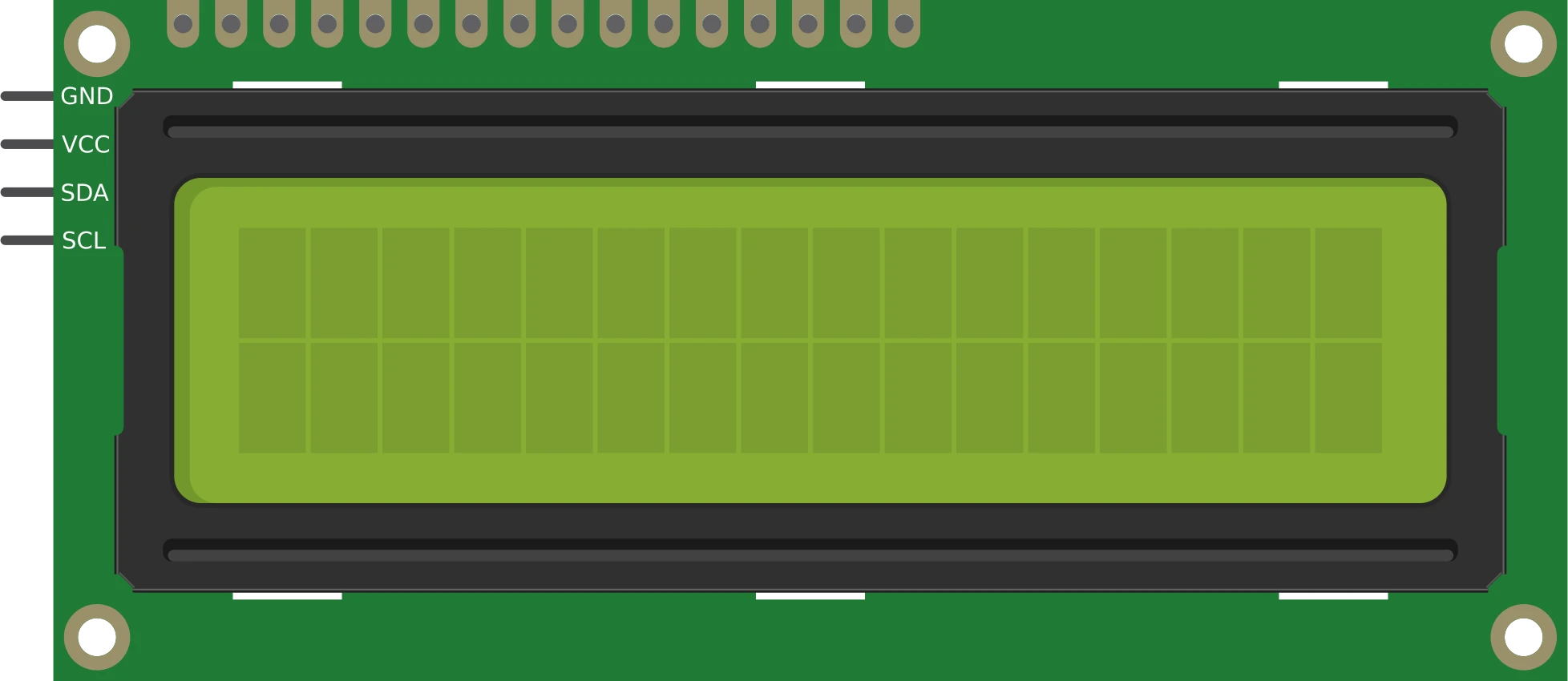
The LCD 1602 I²C is a monochrome character display that shows 16 characters across 2 lines (32 cells total), built on an HD44780-compatible controller. A PCF8574 I²C I/O expander is soldered to the back as a 'backpack', converting the LCD's parallel interface into a two-wire I²C bus. That drops the wiring down to four connections: VCC, GND, SDA, and SCL.
Each cell renders a glyph on a 5x8 dot matrix pulled from the controller's built-in character ROM, and up to eight custom glyphs can be defined in the controller's CGRAM. It cannot draw arbitrary pixels or graphics: it is a text-and-symbol display only. The module runs on 5V, which the HD44780 controller needs to produce readable contrast.
The backpack answers at a fixed I²C address (0x27 on the common PCF8574T version; some units built on the PCF8574A variant answer at 0x3F). A small trimpot on the back sets display contrast, and a jumper controls the backlight. Because it lives on the shared I²C bus, it coexists with other I²C peripherals on the same SDA and SCL lines. The board measures roughly 80 x 36 x 12 mm.
| Pin | Function | Type |
|---|---|---|
GND GND | Power | Power in |
VCC VCC (5V) | Power | Power in |
SDA SDA | I²C SDA | Bidirectional (GPIO) |
SCL SCL | I²C SCL | Bidirectional (GPIO) |
Verified from the Tinkered component library.
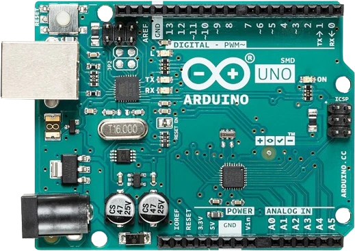
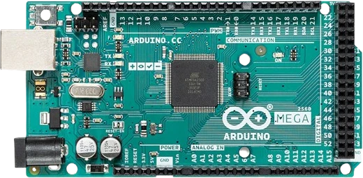
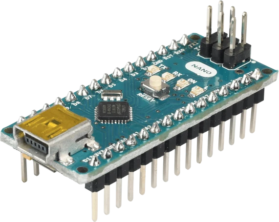
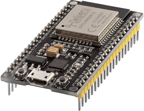
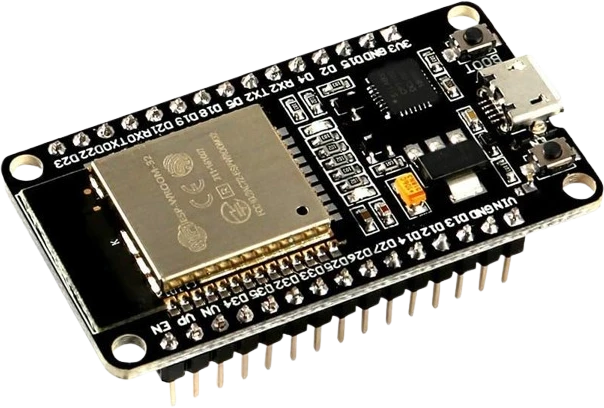
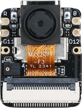
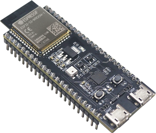
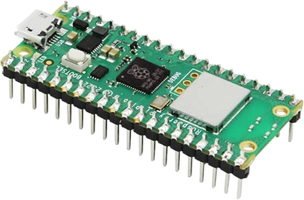
The LCD 1602 I²C connects to any of the microcontrollers supported in Tinkered. Mind the 5 V logic level on 3.3 V boards.
The LCD 1602 I²C is fully simulated in Tinkered. Wire it into a circuit, write your firmware, and read real values back with no physical hardware. Test your logic before you touch a breadboard.
Open it in the simulatorThe display stays blank when the code targets an address the module does not use. A 0x27 board addressed as 0x3F (or vice versa) shows nothing. Run an I²C scanner sketch first and use the address it reports.
Fresh modules often ship with contrast at an extreme, so you see two rows of solid blocks, faint ghost text, or a completely blank panel even though the code is correct. Turn the small potentiometer on the back until characters appear.
The HD44780 controller needs 5V for usable contrast. Wired to a 3.3V rail the backlight may glow but the text is invisible or extremely dim. Feed VCC from 5V and only the logic lines from the 3.3V microcontroller.
The backpack pulls SDA and SCL up to VCC. If VCC is 5V and the microcontroller (ESP32, STM32, etc.) is not 5V tolerant, the I²C lines can exceed the safe input voltage. Use a level shifter or power the backpack pull-ups appropriately in that case.
The backlight is controlled by a removable jumper on the backpack. If that jumper is missing or the transistor pins are shorted, the backlight stays off and the module looks dead even when it is running fine.
Display live temperature, humidity, or distance from a sensor like a DHT22 or HC-SR04 on line 1 and 2, refreshed in the loop.
Pair with an RTC module on the same I²C bus to show time and date without the LCD hogging extra pins.
Combine with a rotary encoder or push buttons to build a scrollable menu, using the eight custom CGRAM characters for arrows and icons.
Share SDA and SCL with other I²C peripherals so one two-wire bus feeds the display plus sensors, expanders, or an RTC at once.
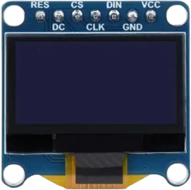
oled-128x64Monochrome I²C display
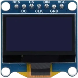
oled-sh1107-128x128Square monochrome OLED
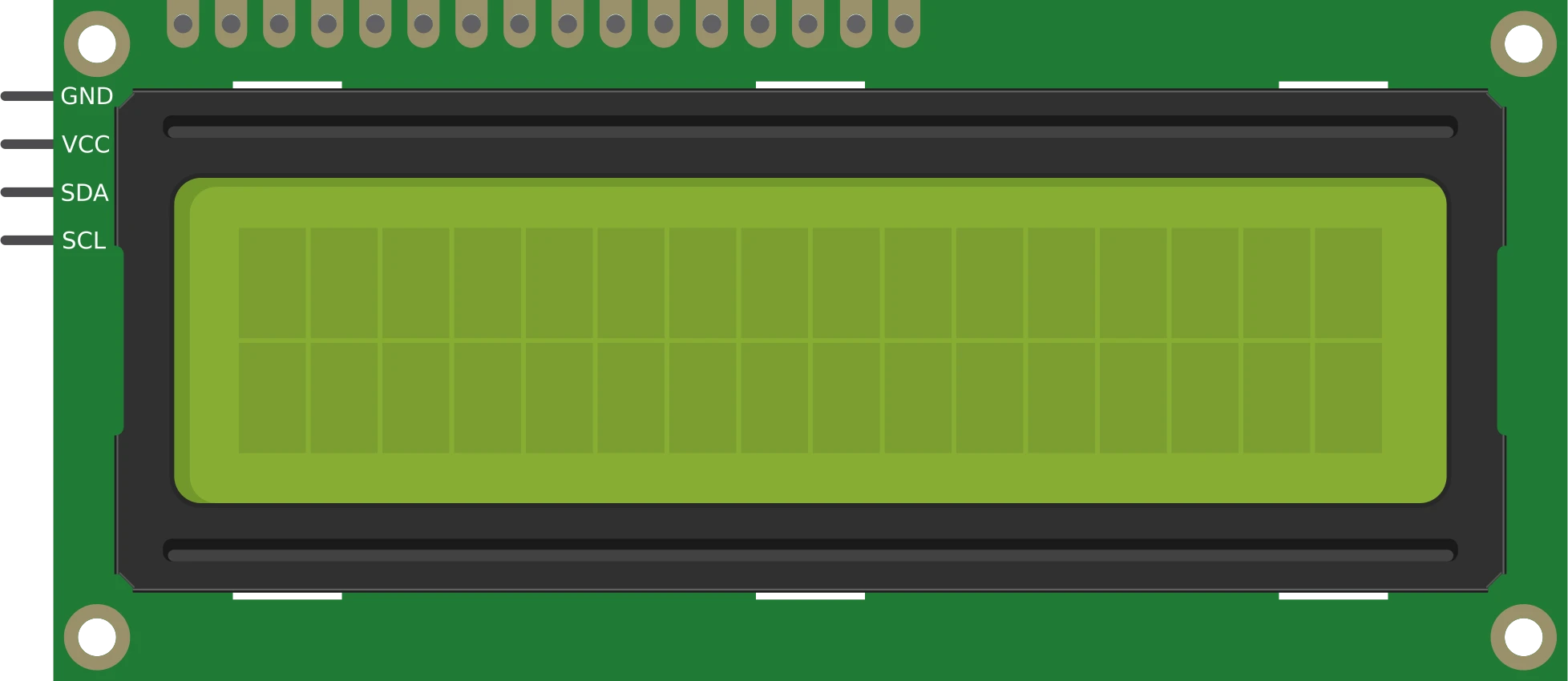
lcd-1602-parallel16×2 character display
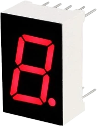
7seg-displaySingle numeric digit
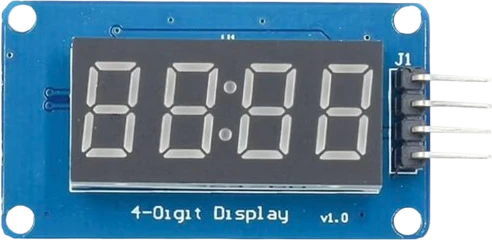
tm1637-4digit-displayFour-digit segment module
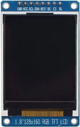
st7735-tft-1-8Color SPI display
Drop the LCD 1602 I²C into a circuit, write firmware, and simulate it in your browser, then deploy to real hardware. All in one editable Tinkered project.