Single-digit counter
Count 0-9 on button presses or a sensor trigger, cycling through the segment patterns for each numeral.
A single-digit numeric LED display: seven individually addressable bar segments plus a decimal point, wired as common-cathode LEDs.
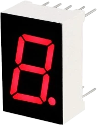
A 7-segment display packs seven bar-shaped LEDs, labeled a through g and arranged in a figure-8, plus a decimal-point LED, into one digit position. Lighting different combinations forms the numerals 0-9 and a handful of letters (such as A-F for hexadecimal). This is the common single-digit module, roughly 12.7mm wide and 19mm tall, with 10 pins broken out.
Each segment is an independent LED with a forward voltage of about 2V, so every segment needs its own current-limiting resistor. In this common-cathode variant, all eight cathodes join at the shared common pins: you tie the common to ground and drive each segment's anode pin HIGH to turn that segment on. The two common pins (com and com2) are internally connected, so grounding either one is enough.
Because the part exposes every segment directly, driving all eight lines from a microcontroller consumes eight I/O pins plus eight resistors. To save pins, builders commonly feed the display from a shift register (74HC595) or a dedicated driver (MAX7219), and multiplex multiple digits by rapidly switching their common lines.
| Pin | Function | Type |
|---|---|---|
e Segment E | Passive | Passive |
d Segment D | Passive | Passive |
com Common (-) | Passive | Passive |
c Segment C | Passive | Passive |
dp Decimal Pt. | Passive | Passive |
b Segment B | Passive | Passive |
a Segment A | Passive | Passive |
f Segment F | Passive | Passive |
g Segment G | Passive | Passive |
com2 Common 2 (-) | Passive | Passive |
Verified from the Tinkered component library.
The 7-Segment Display connects to any of the microcontrollers supported in Tinkered.
The 7-Segment Display is fully simulated in Tinkered. Wire it into a circuit, write your firmware, and read real values back with no physical hardware. Test your logic before you touch a breadboard.
Open it in the simulatorThe two variants use inverted drive logic. A common-cathode part grounds the common and lights a segment by driving its pin HIGH; wire it as if it were common anode and nothing (or everything) lights. Verify the type first.
Sharing one resistor on the common line makes brightness change with how many segments are on, because the current splits across them. Give every segment and the decimal point its own series resistor instead.
Connecting a segment directly to a GPIO pin exceeds both the LED's forward current and the pin's source/sink limit, and can damage the pin or the segment. Always include the series resistor.
When multiplexing digits, the common carries the summed current of every lit segment (up to ~160mA), well beyond a microcontroller pin. Switch the common through a transistor or driver, not straight from a GPIO.
The physical pin sequence does not follow the segment letters, and the two common pins sit in the middle of each row. Map pins from the datasheet rather than guessing, or the digit displays garbled patterns.
Count 0-9 on button presses or a sensor trigger, cycling through the segment patterns for each numeral.
Show a one-digit countdown that decrements each second, lighting the decimal point as a status indicator.
Display a random value from 1 to 6 on each press, a classic first project for learning segment lookup tables.
Flash a digit and measure how fast the player responds, using the display for the round number and score.
Chain several digits driven through a 74HC595 or MAX7219 to build clocks and counters while saving microcontroller pins.
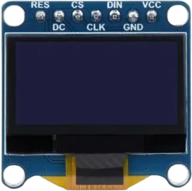
oled-128x64Monochrome I²C display
oled-sh1107-128x128Square monochrome OLED
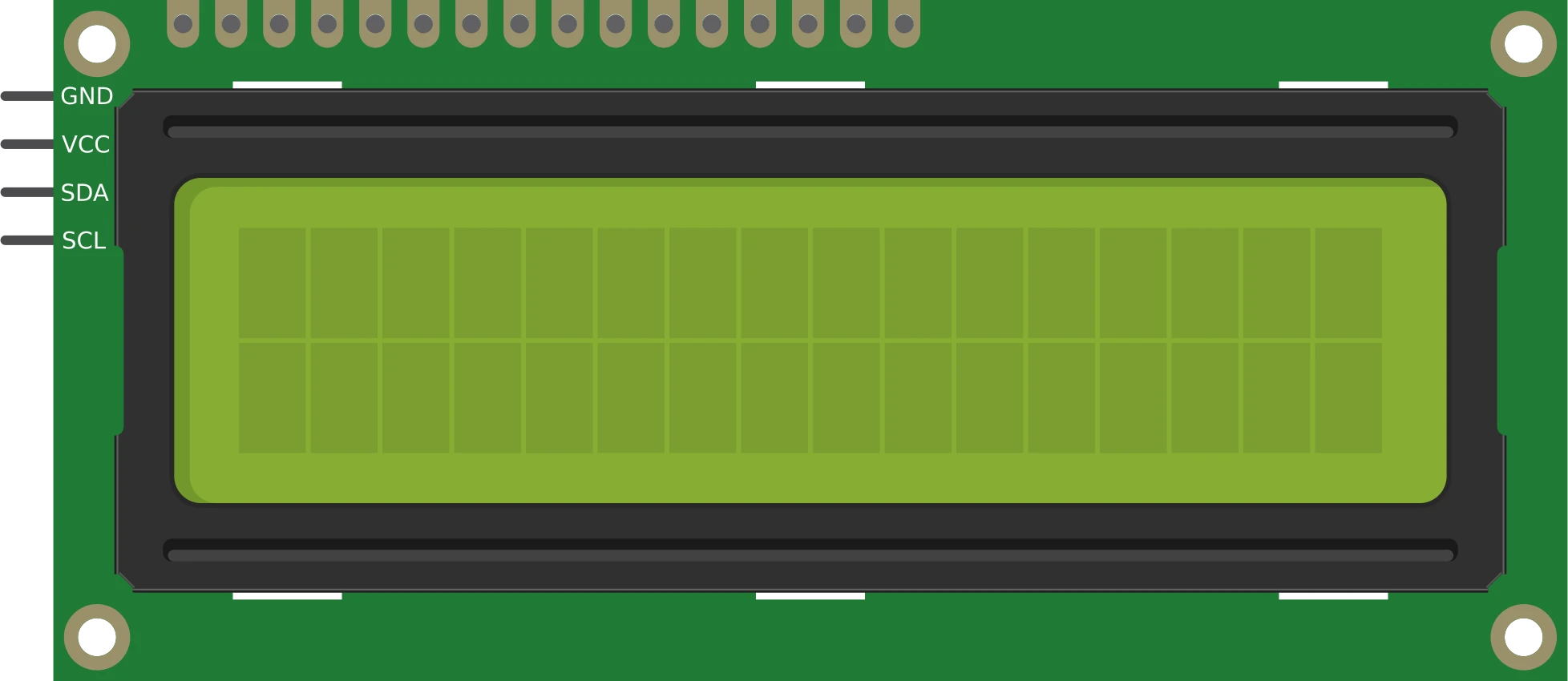
lcd-1602-i2c16×2 character display
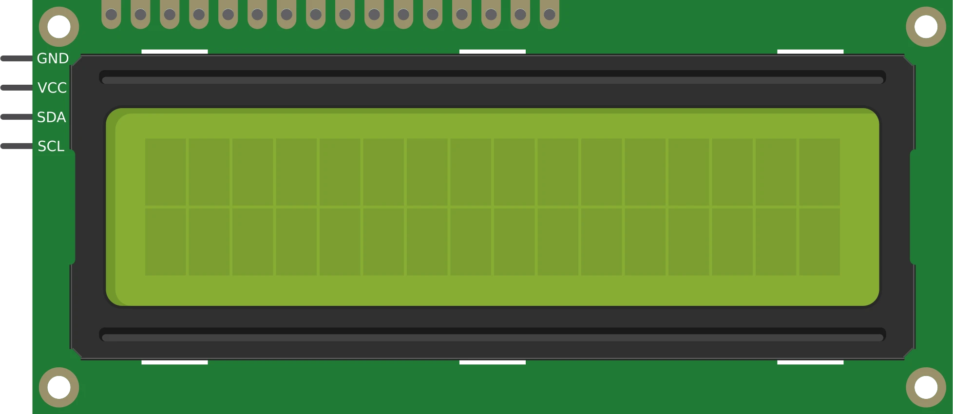
lcd-1602-parallel16×2 character display
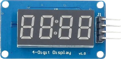
tm1637-4digit-displayFour-digit segment module
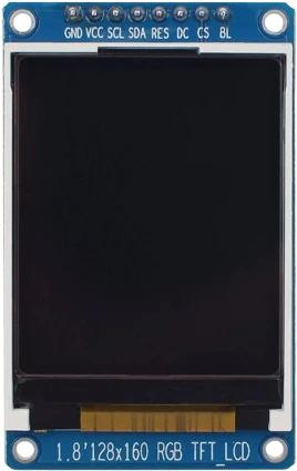
st7735-tft-1-8Color SPI display
Drop the 7-Segment Display into a circuit, write firmware, and simulate it in your browser, then deploy to real hardware. All in one editable Tinkered project.