ESP32-C3 SuperMini
A thumb-sized ESP32-C3 board with Wi-Fi, Bluetooth LE 5 and native USB-C, built around a 160 MHz RISC-V core.
- ChipESP32-C3, single-core 32-bit RISC-V, up to 160 MHz
- Chip memory400 KB SRAM (16 KB cache), 384 KB ROM
- Board flash4 MB
- Wireless2.4 GHz Wi-Fi 802.11b/g/n, Bluetooth 5 (LE), no Bluetooth Classic
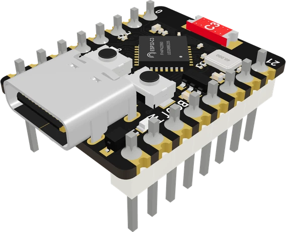
The ESP32-C3 SuperMini is a tiny board around Espressif's ESP32-C3, a single-core 32-bit RISC-V chip at up to 160 MHz with 400 KB SRAM, 2.4 GHz Wi-Fi and Bluetooth 5 (LE) (ESP32-C3 datasheet v2.4, pp. 3, 4). Power it over USB-C or 5 V, wire parts to its 3.3 V GPIO (the chip runs from 3.0 V to 3.6 V, datasheet p. 54), and read analog sensors on GPIO0 to GPIO4, the ADC1 channels (p. 21). Its blue LED is on GPIO8, lit when the pin is LOW, and serial output reaches the computer through the chip's own USB, so build with USB CDC on boot enabled.
The ESP32-C3 SuperMini is one of the smallest and cheapest ways to put Wi-Fi and Bluetooth LE into a project. It is sold under the Nologo and Tenstar names and by many clone makers, and carries an ESP32-C3 with 4 MB of flash, a small ceramic chip antenna, a USB-C socket, BOOT and RESET buttons, a power LED and a blue user LED. Two rows of eight pins break out 13 GPIO plus 5V, GND and 3V3.
The chip is Espressif's ESP32-C3: a single-core 32-bit RISC-V CPU at up to 160 MHz with 400 KB of SRAM (16 KB of it cache) and 384 KB of ROM, a 2.4 GHz 802.11b/g/n Wi-Fi radio and Bluetooth 5 (LE) with mesh support (ESP32-C3 datasheet v2.4, pp. 3, 4). There is no Bluetooth Classic, so libraries such as BluetoothSerial do not apply. Peripherals include two UARTs, I2C, I2S, three SPI controllers, a six-channel LED PWM controller, an RMT with two transmit channels and two 12-bit SAR ADCs (p. 4).
The USB-C port is wired straight to the C3's built-in USB Serial/JTAG controller on GPIO18 and GPIO19 (datasheet p. 48), so there is no separate USB-to-UART chip. That keeps the board small, and it is also the cause of the most common surprise: your sketch must be built with USB CDC on boot enabled, or Serial output goes to UART pins instead of the USB cable. arduino-esp32's own "Nologo ESP32C3 Super Mini" board entry sets this for you, with LED_BUILTIN on GPIO8 and I2C on GPIO8 (SDA) and GPIO9 (SCL).
ESP32-C3 SuperMini pinout
| Pin | Function | Type |
|---|---|---|
| 5V | 5V (VBUS) | power in |
| GND | GND (G) | power in |
| 3V3 | 3V33.3 V | power out |
| IO4 | Digital, PWM, ADC1_CH4, SPI SCK3.3 V | bidirectional |
| IO3 | Digital, PWM, ADC1_CH33.3 V | bidirectional |
| IO2 | Digital, PWM, ADC1_CH2, strapping3.3 V | bidirectional |
| IO1 | Digital, PWM, ADC1_CH13.3 V | bidirectional |
| IO0 | Digital, PWM, ADC1_CH03.3 V | bidirectional |
| IO5 | Digital, PWM, SPI MISO3.3 V | bidirectional |
| IO6 | Digital, PWM, SPI MOSI3.3 V | bidirectional |
| IO7 | Digital, PWM, SPI SS3.3 V | bidirectional |
| IO8 | Digital, PWM, I2C SDA, strapping3.3 V | bidirectional |
| IO9 | Digital, PWM, I2C SCL, strapping3.3 V | bidirectional |
| IO10 | Digital, PWM3.3 V | bidirectional |
| IO20 | Digital, PWM, UART RX3.3 V | bidirectional |
| IO21 | Digital, PWM, UART TX3.3 V | bidirectional |
Specifications
- Chip
- ESP32-C3, single-core 32-bit RISC-V, up to 160 MHzEspressif ESP32-C3 datasheet v2.4, p. 3
- Chip memory
- 400 KB SRAM (16 KB cache), 384 KB ROMEspressif ESP32-C3 datasheet v2.4, p. 4
- Board flash
- 4 MBarduino-esp32 boards.txt, nologo_esp32c3_super_mini.build.flash_size
- Wireless
- 2.4 GHz Wi-Fi 802.11b/g/n, Bluetooth 5 (LE), no Bluetooth ClassicEspressif ESP32-C3 datasheet v2.4, pp. 1, 3
- Chip supply voltage
- 3.0 V to 3.6 V (3.3 V typical)Espressif ESP32-C3 datasheet v2.4, Table 5-2, p. 54
- Analog inputs
- ADC1 on GPIO0 to GPIO4 (factory calibrated); GPIO5 is ADC2Espressif ESP32-C3 datasheet v2.4, pp. 21, 49
- PWM
- LED PWM controller, up to 6 channelsEspressif ESP32-C3 datasheet v2.4, p. 4
- GPIO drive
- 40 mA source (IOH), 28 mA sink (IOL) at the strongest drive settingEspressif ESP32-C3 datasheet v2.4, Table 5-4, p. 55
- Wi-Fi peak current
- Up to 335 mA (802.11b transmit at 21 dBm)Espressif ESP32-C3 datasheet v2.4, Table 5-7, p. 56
- On-board LED
- Blue LED on GPIO8, active LOWZephyr esp32c3_supermini.dts; arduino-esp32 nologo_esp32c3_super_mini variant
- Logic level
- 3.3 V
- Clock speed
- 160 MHz
- Flash
- 4 MB
- RAM
- 400 KB
- GPIO pins
- 13
- ADC channels
- 5
- ADC resolution
- 12 bits
- PWM channels
- 6
- Bluetooth
- BLE 5.0
- Dimensions
- 24.7 × 18 × 13.2 mm
- Weight
- 2 g
From the Generic (Tenstar / Nologo)'s datasheet, published by Generic (Tenstar / Nologo).
Common mistakes
Empty Serial Monitor
The USB-C port is the chip's own USB Serial/JTAG controller. Build with USB CDC on boot enabled (Arduino IDE: "USB CDC On Boot: Enabled", or select the Nologo ESP32C3 Super Mini board; PlatformIO: -DARDUINO_USB_MODE=1 -DARDUINO_USB_CDC_ON_BOOT=1), or Serial goes to the UART pins instead.
Blinking the wrong LED pin
The blue LED is on GPIO8 and is active LOW. On the generic "ESP32C3 Dev Module" board definition LED_BUILTIN does not point at it, so write to pin 8 directly, LOW to turn it on.
Holding a strapping pin LOW at reset
A button, relay board or sensor that pulls GPIO9 LOW at power-up starts the board in download mode, and GPIO8 LOW at the same time stops it booting (ESP32-C3 datasheet v2.4, p. 31). Keep GPIO2, GPIO8 and GPIO9 free or pulled up.
Reading analog values on GPIO5
GPIO5 belongs to ADC2, which has a single uncalibrated channel and does not work on some chip revisions (datasheet p. 49). Use GPIO0 to GPIO4 for analog sensors.
Feeding 5 V signals into a pin
The GPIO are 3.3 V only. A 5 V Echo line, a 5 V UART or a 5 V I2C bus needs a divider or a level shifter.
ESP32-C3 SuperMini questions
Is the ESP32-C3 SuperMini 5 V tolerant?
No. The ESP32-C3's I/O runs from a 3.0 V to 3.6 V supply and its input high level tops out at VDD + 0.3 V (ESP32-C3 datasheet v2.4, pp. 54, 55). You can power the board from 5 V on its 5V pin or USB-C, but every GPIO signal must stay at 3.3 V.
Why won't my ESP32-C3 SuperMini upload or show up on the computer?
Hold BOOT (GPIO9), press and release RESET, then release BOOT: GPIO9 LOW at reset puts the chip in download mode over USB (ESP32-C3 datasheet v2.4, p. 31). Use a USB-C cable that carries data, and check nothing on GPIO8 or GPIO9 is pulling them LOW. If the upload works but the Serial Monitor stays empty, enable USB CDC on boot.
Which pin is the built-in LED on the ESP32-C3 SuperMini?
GPIO8, and it lights when the pin is LOW (Zephyr esp32c3_supermini board file; arduino-esp32 Nologo SuperMini variant). digitalWrite(8, LOW) turns it on.
Which pins can read analog values?
GPIO0 to GPIO4, the five ADC1 channels, which are factory calibrated (ESP32-C3 datasheet v2.4, pp. 21, 49). The calibrated range at the highest attenuation is 0 to 2500 mV (p. 56).
ESP32-C3 SuperMini vs ESP8266: which should I use?
The ESP32-C3 adds Bluetooth 5 (LE), native USB, 400 KB of SRAM and a 160 MHz RISC-V core (ESP32-C3 datasheet v2.4, pp. 3, 4), and runs the same Arduino Wi-Fi libraries through arduino-esp32. Choose the ESP8266 only to reuse existing ESP8266 code or boards; for new Wi-Fi projects the C3 does more for a similar price.
Does the ESP32-C3 SuperMini support Bluetooth Classic or BluetoothSerial?
No. The ESP32-C3 has Bluetooth 5 (LE) and Bluetooth mesh only (ESP32-C3 datasheet v2.4, p. 3). Use BLE libraries such as NimBLE, or a BLE UART service, instead of BluetoothSerial.
ESP32-C3 SuperMini vs XIAO ESP32-C3?
Both use the same chip. The SuperMini has a chip antenna, a blue LED on GPIO8 and 13 GPIO; Seeed's XIAO ESP32C3 has 11 GPIO, a U.FL external antenna, LiPo charging and no user LED (Seeed XIAO ESP32C3 wiki).
Build something with the ESP32-C3 SuperMini
- Build this
Wi-Fi sensor node
Read a temperature or humidity sensor over I2C and publish it to MQTT or Home Assistant.
- Build this
BLE remote or beacon
Advertise sensor values or act as a BLE button for a phone, using the C3's Bluetooth 5 (LE) radio.
- Build this
Tiny NeoPixel controller
Drive a WS2812B strip from one GPIO through the RMT and control it from a web page.
- Build this
Deep-sleep battery logger
Wake on a timer, take a reading, send it over Wi-Fi and go back to sleep at about 5 µA chip current.
This page as plain Markdown, for ChatGPT, Claude or your own agent. /components/esp32-c3-super-mini.md