ESP32-S3-DevKitC-1
Espressif's reference ESP32-S3 board: dual-core 240 MHz, Wi-Fi, Bluetooth LE 5, native USB and a USB-to-UART port.
- ChipESP32-S3, dual-core Xtensa LX7, up to 240 MHz
- Chip memory512 KB SRAM, 384 KB ROM
- Board memory optionsN8, N8R2, N8R8 (WROOM-1/1U); N32R16V (WROOM-2)
- Wireless2.4 GHz Wi-Fi 802.11b/g/n, Bluetooth 5 (LE), no Bluetooth Classic
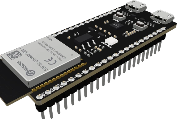
The ESP32-S3-DevKitC-1 is Espressif's development board for the ESP32-S3, a dual-core Xtensa LX7 chip at up to 240 MHz with 512 KB SRAM, 2.4 GHz Wi-Fi and Bluetooth 5 (LE) (ESP32-S3 datasheet v2.2, pp. 3, 4). Power it from either micro-USB port, the 5V pin or the 3V3 pin, one source at a time (DevKitC-1 v1.1 user guide), and wire parts to its 3.3 V GPIO on two 22-pin headers. Its addressable RGB LED is on GPIO38 on v1.1 boards and GPIO48 on v1.0, so drive it as a one-pixel NeoPixel.
The ESP32-S3-DevKitC-1 is the entry-level board Espressif makes for its ESP32-S3. It carries an ESP32-S3-WROOM-1 or WROOM-1U module (or a WROOM-2 on the N32R16V version), a 5 V to 3.3 V LDO, BOOT and RESET buttons, a power LED, an addressable RGB LED and two micro-USB ports. Two 22-pin headers (J1 and J3) break out every available GPIO except the flash SPI bus, and the board can be mounted on a breadboard (DevKitC-1 v1.1 user guide).
The ESP32-S3 is a dual-core Xtensa 32-bit LX7 chip at up to 240 MHz with 512 KB of SRAM, 384 KB of ROM, 45 programmable GPIO, a full-speed USB OTG controller, two 12-bit SAR ADCs with up to 20 channels, 14 capacitive touch pins and an eight-channel LED PWM controller (ESP32-S3 datasheet v2.2, pp. 3 to 5). The radio is 2.4 GHz 802.11b/g/n Wi-Fi with Bluetooth 5 (LE) and mesh; there is no Bluetooth Classic and, unlike the original ESP32, no DAC.
The board comes in several memory versions named after the module: N8 (8 MB flash), N8R2 (8 MB flash and 2 MB quad PSRAM), N8R8 (8 MB flash and 8 MB octal PSRAM) and N32R16V (WROOM-2, 32 MB flash and 16 MB PSRAM), with 1U versions for an external antenna; the N8 and N8R2 versions are end of life (user guide; WROOM-1 datasheet v1.8, p. 3). On octal PSRAM versions GPIO35, GPIO36 and GPIO37 are taken by the memory and must not be used. The two USB ports do different jobs: the USB-to-UART port carries the Serial console and flashing through a bridge chip, while the USB port is the S3's own USB OTG interface, which also supports JTAG debugging.
ESP32-S3-DevKitC-1 pinout
| Pin | Function | Type |
|---|---|---|
| 3V3 | 3V33.3 V | power out |
| 3V3_2 | 3V3 | power out |
| EN | Digital3.3 V | input |
| IO4 | Digital, PWM, ADC1_CH33.3 V | bidirectional |
| IO5 | Digital, PWM, ADC1_CH43.3 V | bidirectional |
| IO6 | Digital, PWM, ADC1_CH53.3 V | bidirectional |
| IO7 | Digital, PWM, ADC1_CH63.3 V | bidirectional |
| IO15 | Digital, PWM, ADC2_CH43.3 V | bidirectional |
| IO16 | Digital, PWM, ADC2_CH53.3 V | bidirectional |
| IO17 | Digital, PWM, ADC2_CH63.3 V | bidirectional |
| IO18 | Digital, PWM, ADC2_CH73.3 V | bidirectional |
| IO8 | Digital, PWM, ADC1_CH7, I2C SDA (default)3.3 V | bidirectional |
| IO3 | Digital, PWM, ADC1_CH2, strapping3.3 V | bidirectional |
| IO46 | Digital, PWM, strapping3.3 V | bidirectional |
| IO9 | Digital, PWM, ADC1_CH8, I2C SCL (default)3.3 V | bidirectional |
| IO10 | Digital, PWM, ADC1_CH9, SPI CS (default FSPI)3.3 V | bidirectional |
| IO11 | Digital, PWM, ADC2_CH0, SPI MOSI (default FSPI)3.3 V | bidirectional |
| IO12 | Digital, PWM, ADC2_CH1, SPI SCK (default FSPI)3.3 V | bidirectional |
| IO13 | Digital, PWM, ADC2_CH2, SPI MISO (default FSPI)3.3 V | bidirectional |
| IO14 | Digital, PWM, ADC2_CH33.3 V | bidirectional |
| 5V | 5V (5V0) | power in |
| GND | GND (G) | power in |
| GND_2 | GND (G) | power in |
| IO43 | Digital, PWM, UART U0TXD3.3 V | bidirectional |
| IO44 | Digital, PWM, UART U0RXD3.3 V | bidirectional |
| IO1 | Digital, PWM, ADC1_CH03.3 V | bidirectional |
| IO2 | Digital, PWM, ADC1_CH13.3 V | bidirectional |
| IO42 | Digital, PWM3.3 V | bidirectional |
| IO41 | Digital, PWM3.3 V | bidirectional |
| IO40 | Digital, PWM3.3 V | bidirectional |
| IO39 | Digital, PWM3.3 V | bidirectional |
| IO38 | Digital, PWM3.3 V | bidirectional |
| IO37 | Digital, PWM3.3 V | bidirectional |
| IO36 | Digital, PWM3.3 V | bidirectional |
| IO35 | Digital, PWM3.3 V | bidirectional |
| IO0 | Digital, PWM, strapping3.3 V | bidirectional |
| IO45 | Digital, PWM, strapping3.3 V | bidirectional |
| IO48 | Digital, PWM3.3 V | bidirectional |
| IO47 | Digital, PWM3.3 V | bidirectional |
| IO21 | Digital, PWM3.3 V | bidirectional |
| IO20 | Digital, PWM, ADC2_CH93.3 V | bidirectional |
| IO19 | Digital, PWM, ADC2_CH83.3 V | bidirectional |
| GND_3 | GND (G) | power in |
| GND_4 | GND (G) | power in |
Specifications
- Chip
- ESP32-S3, dual-core Xtensa LX7, up to 240 MHzEspressif ESP32-S3 datasheet v2.2, p. 3
- Chip memory
- 512 KB SRAM, 384 KB ROMEspressif ESP32-S3 datasheet v2.2, p. 4
- Board memory options
- N8, N8R2, N8R8 (WROOM-1/1U); N32R16V (WROOM-2)ESP32-S3-DevKitC-1 v1.1 user guide, ordering information
- Wireless
- 2.4 GHz Wi-Fi 802.11b/g/n, Bluetooth 5 (LE), no Bluetooth ClassicEspressif ESP32-S3 datasheet v2.2, pp. 1, 3
- Chip supply voltage
- 3.0 V to 3.6 V (3.3 V typical)Espressif ESP32-S3 datasheet v2.2, Table 5-2, p. 64
- ADC
- Two 12-bit SAR ADCs, up to 20 channels; ADC2 not usable while Wi-Fi is onEspressif ESP32-S3 datasheet v2.2, pp. 5, 59
- PWM and touch
- LED PWM up to 8 channels; 14 capacitive touch pinsEspressif ESP32-S3 datasheet v2.2, pp. 4, 5
- Headers
- J1 and J3, 22 pins each (44 in all)ESP32-S3-DevKitC-1 v1.1 user guide, header block
- RGB LED
- Addressable RGB LED on GPIO38 (v1.1), GPIO48 (v1.0)ESP32-S3-DevKitC-1 v1.1 user guide, hardware revision details
- Wi-Fi peak current
- Up to 340 mA (802.11b transmit at 21 dBm)Espressif ESP32-S3 datasheet v2.2, p. 66
- Logic level
- 3.3 V
- Clock speed
- 240 MHz
- Flash
- 8 MB
- RAM
- 512 KB
- GPIO pins
- 36
- ADC channels
- 20
- ADC resolution
- 12 bits
- PWM channels
- 8
- Bluetooth
- BLE 5.0
- Dimensions
- 69.6 × 25.4 × 12.9 mm
- Weight
- 8 g
From the Espressif's datasheet, published by Espressif.
Common mistakes
Driving the RGB LED like a plain LED
The LED is an addressable RGB LED on GPIO38 on v1.1 boards (GPIO48 on v1.0). digitalWrite(38, HIGH) does nothing useful; use neopixelWrite(38, r, g, b) in arduino-esp32 or a NeoPixel library with one pixel.
Using classic ESP32 pin habits
The ESP32-S3 has no DAC, so dacWrite() fails, and its pin map differs from the original ESP32: there is no GPIO22 to GPIO25. Check every pin against the S3 pinout before reusing an ESP32 sketch.
Using GPIO35 to GPIO37 on an octal PSRAM board
On N8R8 and WROOM-2 boards these pins carry the flash and PSRAM bus (DevKitC-1 v1.1 user guide). Wiring a part to them crashes or corrupts the board.
Plugging into the wrong USB port
The USB-to-UART port carries the default Serial console and flashing. The other port is the S3's native USB: use it for USB HID, USB CDC or JTAG debugging, and expect it to re-enumerate on reset.
Analog reads that stop when Wi-Fi starts
ADC2 cannot be used while Wi-Fi is active (ESP32-S3 datasheet v2.2, p. 59). Move the sensor to an ADC1 pin, GPIO1 to GPIO10.
ESP32-S3-DevKitC-1 questions
Is the ESP32-S3-DevKitC-1 5 V tolerant?
No. The board takes 5 V on its 5V pin or USB, but the ESP32-S3's I/O runs from a 3.0 V to 3.6 V supply with inputs rated to VDD + 0.3 V (ESP32-S3 datasheet v2.2, pp. 64, 65). Keep every GPIO signal at 3.3 V.
Why won't my ESP32-S3-DevKitC-1 upload?
Hold BOOT, press RESET, then release BOOT to enter firmware download mode (DevKitC-1 v1.1 user guide). Upload through the USB-to-UART port with a cable that carries data, and make sure nothing pulls GPIO0, GPIO3, GPIO45 or GPIO46 at reset, since those are strapping pins (datasheet p. 26).
Which pin is the RGB LED on the ESP32-S3-DevKitC-1?
GPIO38 on v1.1 boards and GPIO48 on the original v1.0 (DevKitC-1 v1.1 user guide). It is an addressable RGB LED, so send it colour data with neopixelWrite() or a NeoPixel library.
What is the difference between the two USB ports?
The USB-to-UART port goes through a bridge chip at up to 3 Mbps and is used for power, flashing and the Serial console. The USB port is the ESP32-S3's full-speed USB OTG interface, which can act as a keyboard, mouse or USB serial device and supports JTAG debugging (DevKitC-1 v1.1 user guide).
ESP32-S3 vs ESP32: what changed?
The S3 has LX7 cores at up to 240 MHz with vector instructions, native USB OTG, 45 GPIO and 14 touch pins (ESP32-S3 datasheet v2.2, pp. 3 to 5). It drops Bluetooth Classic and the DAC, and its pin numbers differ, so classic ESP32 sketches often need new pins.
Does the ESP32-S3-DevKitC-1 have PSRAM?
Depends on the version: N8 has none, N8R2 has 2 MB of quad PSRAM, N8R8 has 8 MB of octal PSRAM and N32R16V has 16 MB (DevKitC-1 v1.1 user guide; WROOM-1 datasheet v1.8, p. 3). The module's marking tells you which you have.
Build something with the ESP32-S3-DevKitC-1
- Build this
USB keyboard or macro pad
Use the S3's native USB to act as a keyboard, mouse or MIDI device with buttons and an encoder.
- Build this
Voice or audio project
Read an I2S microphone and play through an I2S amplifier, with PSRAM for audio buffers.
- Build this
Wi-Fi dashboard display
Drive an SPI TFT with live data from the web, using PSRAM for the frame buffer.
- Build this
Edge AI sensor
Run a small TensorFlow Lite Micro model on the LX7 cores to classify sensor or audio data.
- Build this
BLE and Wi-Fi gateway
Collect readings from Bluetooth LE sensors and forward them to MQTT over Wi-Fi.
This page as plain Markdown, for ChatGPT, Claude or your own agent. /components/esp32-s3-devkitc-1.md