Smart water usage monitor
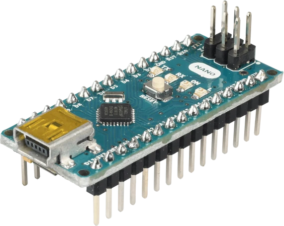
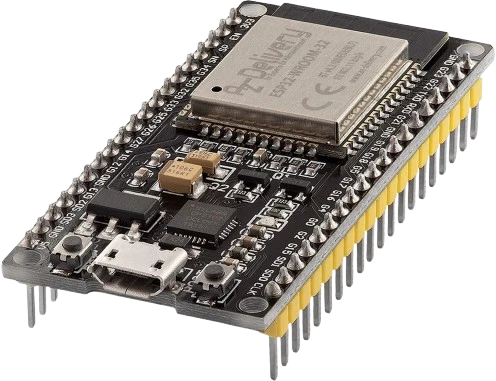
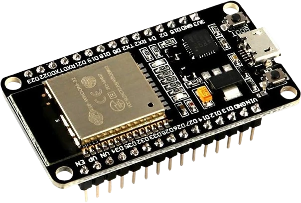
Count pulses on an Arduino or ESP32 and show live flow rate plus cumulative liters on an LCD or OLED, logging daily consumption.
An inline Hall-effect water flow sensor that turns liquid flow into a pulse train, roughly 450 pulses per liter.
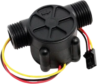
The YF-S201 is a compact inline water flow sensor built around a plastic valve body with 1/2 inch threaded ports, a pinwheel rotor, and a Hall-effect sensor. As water passes through, it spins the rotor, whose embedded magnet sweeps past the Hall sensor and generates a square-wave pulse output. It plugs into a pipe run and reports flow without any moving electrical contacts touching the water.
The output appears on the yellow DATA wire as a digital pulse whose frequency tracks flow rate. The sensor produces on the order of 450 pulses per liter, and the frequency follows F(Hz) = 7.5 x Q, where Q is flow in liters per minute. Firmware counts these pulses over a fixed window to derive instantaneous flow rate, and accumulates the count to compute total dispensed volume. It runs from a 5V supply (the red wire is rated up to 12V) and draws only about 15 mA at 5V.
The sensor measures flow from roughly 1 to 30 liters per minute with an accuracy near plus or minus 10 percent, so it is well suited to hobby water metering, dosing, and monitoring rather than billing-grade measurement. Because unit-to-unit tolerance is significant, calibrating the pulses-per-liter factor against a known volume gives noticeably better results.
| Pin | Function | Type |
|---|---|---|
VCC Red: 3.5-12Vdc | Power | Power in |
GND Black: GND | Power | Power in |
DATA Yellow: Hall pulse output | Digital Hall-effect pulse output; about 450 pulses per liter | Digital output |
Verified from the Tinkered component library · Handson Technology / generic YF-S201.
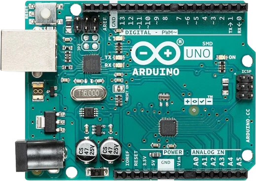
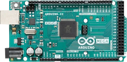
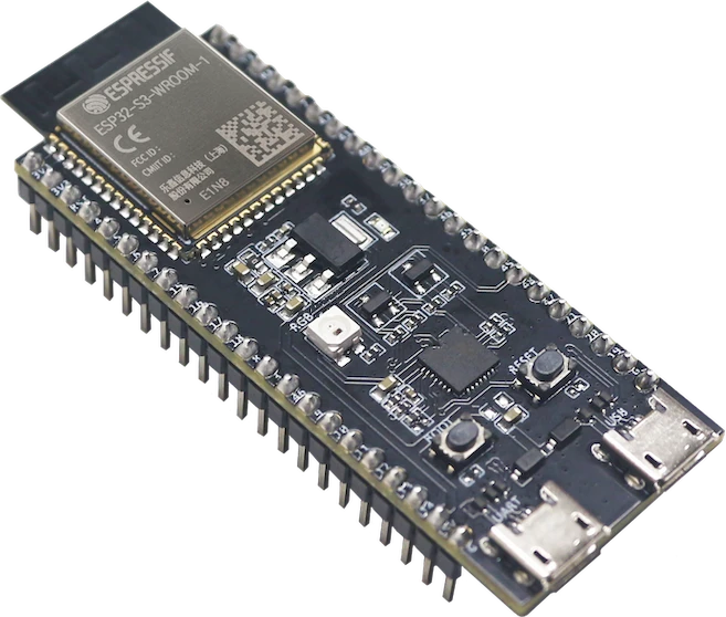
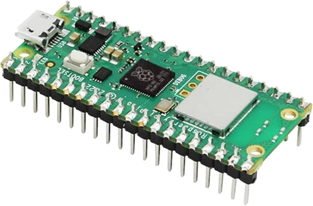
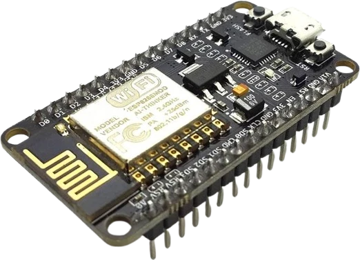
The YF-S201 Water Flow connects to any of the microcontrollers supported in Tinkered. Mind the 5 V logic level on 3.3 V boards.
The YF-S201 Water Flow is fully simulated in Tinkered. Wire it into a circuit, write your firmware, and read real values back with no physical hardware. Test your logic before you touch a breadboard.
Open it in the simulatorPowered at 5V, the DATA line outputs 5V pulses. Wiring that straight into an ESP32, ESP8266, or Raspberry Pi GPIO can damage the input. Use a level shifter or a resistor divider on the signal line.
Reading the pin in a loop misses pulses as flow increases, undercounting volume. Attach a hardware interrupt to the DATA pin and increment a volatile counter, then compute rate from the count over a fixed interval.
The 450 pulses-per-liter and F = 7.5 x Q figures are nominal, and accuracy is only about plus or minus 10 percent per unit. For meaningful volume readings, pass a measured volume through the sensor and adjust the conversion factor to match.
Below roughly 1 L/min the impeller stalls or spins erratically, and trapped air bubbles cause false or dropped pulses. Keep the pipe full, mount the sensor so it stays primed, and stay within the 1 to 30 L/min range.
The Hall output is open-collector, so without a pull-up to the logic rail the input floats and pulses look noisy or absent. Enable the internal pull-up or add an external 10k resistor to VCC.
Count pulses on an Arduino or ESP32 and show live flow rate plus cumulative liters on an LCD or OLED, logging daily consumption.
Pair the sensor with a solenoid valve so the controller shuts the valve once a target volume has passed, perfect for measured plant watering.
Dispense a precise amount of liquid by opening a pump or valve until the pulse count reaches a preset volume, then stopping automatically.
Stream flow data from an ESP8266 or ESP32 to a dashboard to spot unusual usage patterns and flag possible leaks in real time.
Drop the YF-S201 Water Flow into a circuit, write firmware, and simulate it in your browser, then deploy to real hardware. All in one editable Tinkered project.