LED blinker
An astable circuit flashes an LED at a rate set by two resistors and a capacitor. It is the classic first project for learning the 555.
An 8-pin bipolar precision timer IC that generates accurate time delays and oscillation from a single external resistor-capacitor network.
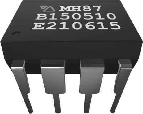
The NE555 is a general-purpose precision timer that produces accurate time delays and oscillation using just an external resistor and capacitor. It runs from a single 4.5-16V supply, and its output can sink or source up to 200 mA, enough to drive LEDs, small relays, and speakers directly without an added buffer stage.
Internally it combines two comparators, an RS flip-flop, an output stage, and a discharge transistor, with a three-resistor divider that fixes the lower trigger point at 1/3 VCC and the upper threshold at 2/3 VCC. Pulling TRIG (pin 2) below 1/3 VCC sets the output high. When THRESH (pin 6) rises past 2/3 VCC the flip-flop resets, the output goes low, and the discharge transistor on pin 7 turns on to drain the timing capacitor.
In monostable (one-shot) mode a single trigger produces one output pulse whose width is t = 1.1 x R x C. In astable mode the chip free-runs as an oscillator at f = 1.44 / ((RA + 2 x RB) x C). The active-low RESET (pin 4) overrides the timing and forces the output low, while CTRL (pin 5) can shift the internal thresholds to fine-tune timing or perform pulse-width modulation.
| Pin | Function | Type |
|---|---|---|
GND 1 GND | Power | Power in |
TRIG 2 TRIG | Analog | Digital input |
OUT 3 OUT | Digital | Digital output |
RESET 4 RESET | Digital | Digital input |
VCC 8 VCC | Power | Power in |
DISCH 7 DISCH | Open collector | Open collector |
THRESH 6 THRESH | Analog | Digital input |
CTRL 5 CTRL | Analog | Digital input |
Verified from the Tinkered component library.
The NE555 Timer connects to any of the microcontrollers supported in Tinkered. Mind the 5 V logic level on 3.3 V boards.
Pin 4 is an active-low reset. If it is left unconnected it picks up noise, and the output can stay low or glitch. Tie it to VCC (directly or through a pull-up resistor) unless you are actively driving it.
Without a 0.01uF capacitor from CTRL (pin 5) to ground, supply noise couples into the comparator reference and modulates the 1/3 and 2/3 VCC thresholds, making the timing jitter.
The output stage produces large, brief current surges as it switches. Skipping a 0.1uF capacitor across VCC and GND leads to false triggering and double pulses, which is especially common on breadboards.
In the classic two-resistor astable circuit the capacitor charges through RA plus RB but discharges only through RB, so the high time is always longer than the low time. Reaching a true 50% duty cycle requires a steering diode or a different topology.
A very low RA forces a large current through the discharge transistor during the low phase, wasting power and stressing the part. Keep the timing resistors above roughly 1k ohm.
An astable circuit flashes an LED at a rate set by two resistors and a capacitor. It is the classic first project for learning the 555.
An astable stage with a potentiometer varies the duty cycle and drives a transistor or MOSFET to dim an LED strip or control a small motor.
Running astable in the audio range, the output drives a small speaker or piezo to make beeps, alarms, and sirens.
A monostable circuit produces one fixed-length output pulse (t = 1.1 x R x C) from a momentary trigger, useful for delayed relays and timed loads.
A low-frequency astable oscillator produces steady audible clicks whose tempo is set by a variable resistor.
Drop the NE555 Timer into a circuit, write firmware, and simulate it in your browser, then deploy to real hardware. All in one editable Tinkered project.