555 timer blinker or PWM generator
The classic DIP-8 NE555 in astable or monostable mode drives LED flashers, tone generators, and simple pulse-width dimming.
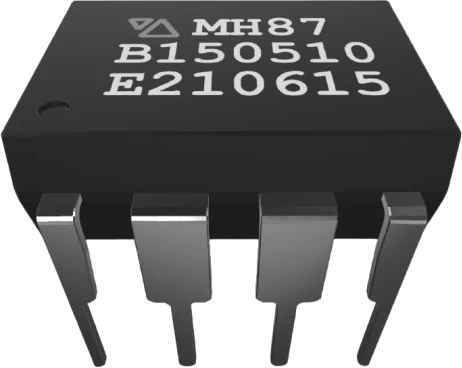
A standard 8-pin dual in-line (DIP-8) package outline for through-hole chips, the breadboard-friendly footprint behind 555 timers, dual op-amps, serial EEPROMs, and small microcontrollers.
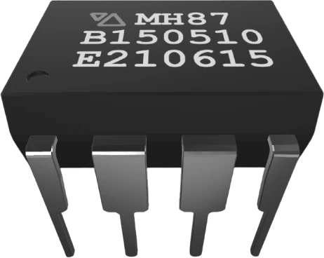
DIP-8 (also written PDIP-8 or DIP8) is a package standard rather than a specific chip. It has eight leads arranged in two parallel rows of four, on a 0.1 inch (2.54mm) pin pitch with the rows spaced 0.3 inch (7.62mm) apart, conforming to the JEDEC MS-001 narrow-body outline. The molded body measures roughly 9.8mm long by 6.35mm wide and stands about 3.3mm tall, so the part straddles the center trench of a solderless breadboard with one row of pins on each side.
Because this entry is generic, the individual pin functions are left unspecified. Pin 1 is identified by a notch or a molded dot at one end of the body, and pins are numbered counterclockwise when the chip is viewed from above. What each pin actually does depends entirely on the part fitted into the package: the NE555 timer, the LM358 dual op-amp, the ATtiny85 microcontroller, and the 24LC256 I2C EEPROM all share this outline but have completely different pinouts.
Treat this component as a stand-in when you want the physical DIP-8 footprint in a layout or schematic. For a real build, pull the datasheet for the exact part number to get the supply voltage range, the VCC and GND pin locations, and any required support components.
| Pin | Function | Type |
|---|---|---|
1 Pin 1 | — | — |
2 Pin 2 | — | — |
3 Pin 3 | — | — |
4 Pin 4 | — | — |
5 Pin 5 | — | — |
6 Pin 6 | — | — |
7 Pin 7 | — | — |
8 Pin 8 | — | — |
Verified from the Tinkered component library.
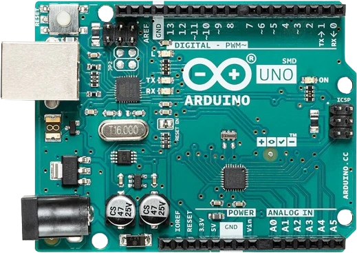
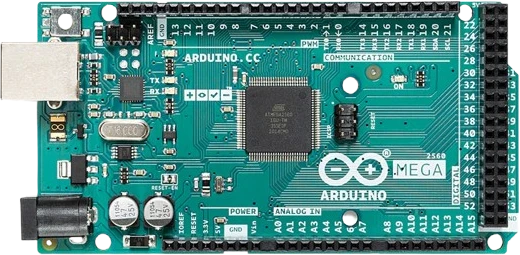
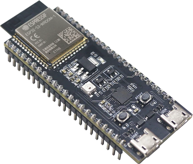
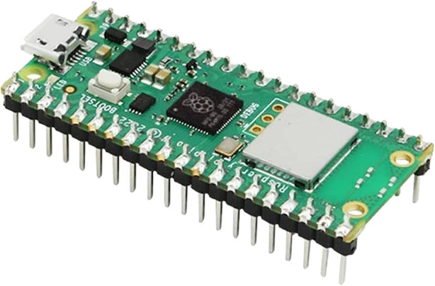
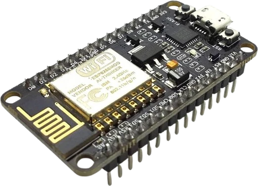
The Generic DIP-8 IC connects to any of the microcontrollers supported in Tinkered.
The body notch or dot marks pin 1, and pins run counterclockwise from there. Seating the package rotated 180 degrees swaps power and ground on most parts, which usually destroys the chip the moment you apply voltage.
There is no shared power convention for 8-pin chips. An NE555 puts VCC on pin 8 and GND on pin 1, while an LM358 uses V+ on pin 8 and GND on pin 4. Confirm the supply pins from the actual datasheet every time.
Skipping the 0.1uF cap across the supply pins invites glitches, jitter, and oscillation, which is especially visible on 555 timing and op-amp circuits that sit near a breadboard's noisy rails.
Reprogrammable or delicate parts like the ATtiny85 are far easier to work with in a socket. Soldering the DIP straight to the board makes reprogramming or replacement a desoldering job.
DIP-8 is through-hole on a 0.3 inch row spacing. It will not fit an SOIC-8 surface-mount footprint or a 0.6 inch wide DIP layout, so match the package to the board's footprint before ordering.
The classic DIP-8 NE555 in astable or monostable mode drives LED flashers, tone generators, and simple pulse-width dimming.
An LM358 or TL072 in a DIP-8 handles microphone preamps, active filters, and sensor buffering with two op-amps in one package.
The 8-pin ATtiny85 is Arduino-programmable and popular for tiny standalone gadgets, wearables, and I/O expanders where a full Uno is overkill.
A 24LCxxx serial EEPROM in DIP-8 adds nonvolatile memory to a microcontroller over just two I2C lines for logging and configuration data.
Parts like the PC817 or 4N26 in a DIP-8 provide galvanic isolation between a low-voltage controller and a higher-voltage or mains-adjacent load.
Drop the Generic DIP-8 IC into a circuit, write firmware, and simulate it in your browser, then deploy to real hardware. All in one editable Tinkered project.