Two-wheel robot car
Drive the left and right gear motors from channels A and B for a differential-drive chassis with independent speed and direction on each side.
Toshiba dual H-bridge motor driver that runs two DC motors (or one bipolar stepper) at 1.2A continuous per channel using MOSFET outputs.
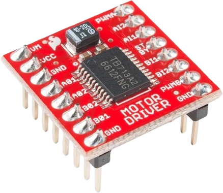
The TB6612FNG is a dual H-bridge motor driver from Toshiba built around MOSFET output stages. On a SparkFun-style carrier it exposes two independent channels, A and B, each able to drive one brushed DC motor, while the two channels together can drive a single bipolar stepper. Each channel delivers 1.2A of continuous current and tolerates peaks up to 3.2A.
Each channel is steered by two direction inputs (AIN1/AIN2 for channel A, BIN1/BIN2 for channel B) plus a dedicated PWM speed input (PWMA and PWMB). The direction pins select one of four states: forward, reverse, short brake, and stop, and the PWM pin (usable up to 100kHz) sets speed. A shared STBY pin enables or disables both bridges at once. Logic runs on VCC of 2.7-5.5V, so the control side interfaces directly with 3.3V and 5V microcontrollers.
Motor power enters on a separate VM rail (up to 13.5V), isolated from the logic supply. Because the outputs are low on-resistance MOSFETs with integrated diodes, the TB6612FNG runs cooler and drops less voltage than older bipolar drivers such as the L298N, and it needs no external flyback diodes. Built-in thermal shutdown and low-voltage detection guard the device during faults.
| Pin | Function | Type |
|---|---|---|
VM VM | Power | Power in |
VCC VCC | Power | Power in |
GND_VM GND | Power | Power in |
A1 A1 | Digital DC motor bridge output | Free |
A2 A2 | Digital DC motor bridge output | Free |
B1 B1 | Digital DC motor bridge output | Free |
B2 B2 | Digital DC motor bridge output | Free |
GND_AUX GND | Power | Power in |
PWMA PWMA | Digital · PWM | Digital input |
AIN2 AIN2 | Digital | Digital input |
AIN1 AIN1 | Digital | Digital input |
STBY STBY | Digital | Digital input |
BIN1 BIN1 | Digital | Digital input |
BIN2 BIN2 | Digital | Digital input |
PWMB PWMB | Digital · PWM | Digital input |
GND_LOGIC GND | Power | Power in |
Verified from the Tinkered component library · Toshiba / SparkFun-style TB6612FNG carrier.
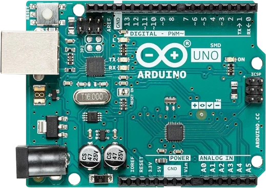
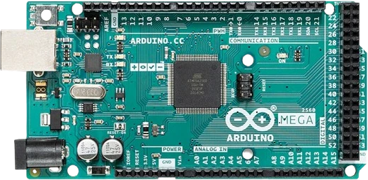
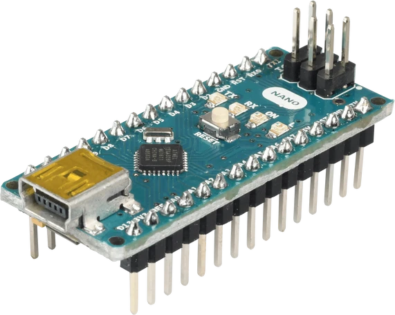
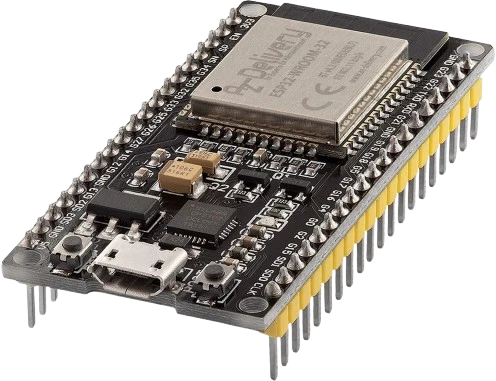
The TB6612FNG Motor Driver connects to any of the microcontrollers supported in Tinkered. Mind the 5 V logic level on 3.3 V boards.
The TB6612FNG Motor Driver is fully simulated in Tinkered. Wire it into a circuit, write your firmware, and read real values back with no physical hardware. Test your logic before you touch a breadboard.
Open it in the simulatorSTBY is an active-high enable. If it is not driven high, both H-bridges stay in standby and the motors never move no matter what the direction or PWM pins do. Tie STBY to a GPIO you set high, or pull it up to VCC.
The logic ground, the motor supply ground, and the microcontroller ground must all connect. Without a shared reference the direction and PWM signals are undefined relative to the driver, causing erratic or dead outputs.
VM is the motor supply (up to 13.5V) and VCC is the logic supply (2.7-5.5V). Powering the logic from the motor rail, or exceeding 5.5V on VCC, can damage the IC. Keep the two rails separate and within range.
A motor whose stall current tops 1.2A continuous or 3.2A peak will trip the thermal shutdown or overheat the driver. Check the motor's stall current, and parallel the A and B channels when one motor needs more headroom.
Both inputs high is short brake and both low is stop, so neither produces rotation. Motion requires complementary levels on AIN1/AIN2 (or BIN1/BIN2) together with the PWM pin held high.
Drive the left and right gear motors from channels A and B for a differential-drive chassis with independent speed and direction on each side.
Pair the driver with IR or ultrasonic sensors so an Arduino can steer a small bot by adjusting the PWMA and PWMB duty cycles in real time.
Use both channels together to energize the two coils of a small bipolar stepper for precise positioning in a pan-tilt rig or mini CNC axis.
Run a single DC motor with smooth PWM speed control while keeping the second channel free for a pump, actuator, or second motor.
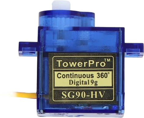
servo-sg90Compact positional servo
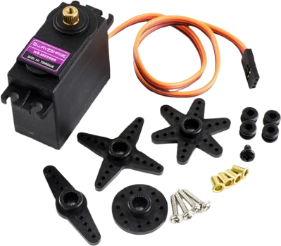
servo-mg996r-straightHigh-torque servo variant
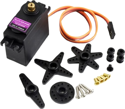
servo-mg996r-crossHigh-torque servo variant
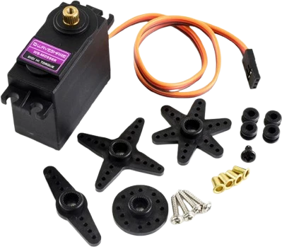
servo-mg996r-starHigh-torque servo variant
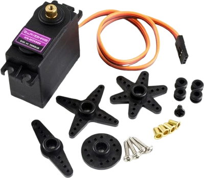
servo-mg996r-roundHigh-torque servo variant
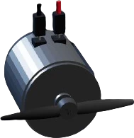
dc-motorBrushed direct-current motor
Drop the TB6612FNG Motor Driver into a circuit, write firmware, and simulate it in your browser, then deploy to real hardware. All in one editable Tinkered project.