Raspberry Pi Pico 2
Raspberry Pi's second Pico: the RP2350 with two Arm Cortex-M33 or two Hazard3 RISC-V cores at 150 MHz, 520 KB SRAM and 4 MB flash, on the same 40-pin 51 x 21 mm board as the original Pico.
- Chip and coresRP2350A: dual Arm Cortex-M33 or dual Hazard3 RISC-V, up to 150 MHz
- Memory520 KB on-chip SRAM; 4 MB QSPI flash on the board
- RadioNone; the Pico 2 W adds Wi-Fi and Bluetooth
- I/O voltage3.3 V GPIO; 5 V tolerant while IOVDD is powered (up to 5.5 V on fault-tolerant pins), except ADC-capable pins, which are limited to IOVDD + 0.5 V
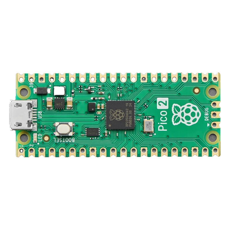
The Raspberry Pi Pico 2 is a 51 x 21 mm board with the RP2350A: two Cortex-M33 or Hazard3 RISC-V cores at up to 150 MHz, 520 KB SRAM, 4 MB QSPI flash, 26 GPIOs of which three are ADC inputs, and micro-USB (Pico 2 datasheet, pp. 3 to 4, 7). It runs from 1.8 to 5.5 V on VSYS through an RT6150 buck-boost converter, and its 3V3 pin should carry less than 300 mA of external load (datasheet pp. 9, 15). The GPIOs are 3.3 V but, unlike the RP2040's, 5 V tolerant while the chip is powered, except the ADC pins GP26 to GP28 (RP2350 datasheet).
The Pico 2 keeps the original Pico's footprint, pinout and castellated edge, so carrier boards, cases and most code carry over, and upgrades the chip: 150 MHz instead of 133 MHz, 520 KB of SRAM instead of 264 KB, and 4 MB of flash instead of 2 MB (Pico 2 datasheet, p. 6). At boot you choose which pair of cores runs, Arm Cortex-M33 with a floating-point unit and TrustZone, or Raspberry Pi's open Hazard3 RISC-V.
Four RP2350 pins are kept for the board itself: GPIO23 sets the regulator's power-save mode, GPIO24 senses VBUS, GPIO25 drives the green LED and GPIO29 reads VSYS/3 on ADC channel 3 (datasheet p. 7). The 12-bit, 500 ksps ADC uses the filtered 3.3 V rail as its reference on ADC_VREF; an external 3.0 V shunt reference there improves accuracy (datasheet pp. 4, 14).
Programming is drag and drop: hold BOOTSEL while plugging in USB and the board appears as a drive for UF2 files, and the Arduino-Pico core does this automatically after the first time. Three SWD pads at the end give a debugger full access (datasheet pp. 3, 5).
Raspberry Pi Pico 2 pinout
| Pin | Function | Type |
|---|---|---|
| GP0 | GPIO0, UART0 TX (Serial1), I2C0 SDA, SPI0 RX, PWM0 A3.3 V, 5 V tolerant when powered | bidirectional |
| GP1 | GPIO1, UART0 RX (Serial1), I2C0 SCL, SPI0 CSn, PWM0 B3.3 V, 5 V tolerant when powered | bidirectional |
| GND | GND | passive |
| GP2 | GPIO2, I2C1 SDA, SPI0 SCK, PWM1 A3.3 V, 5 V tolerant when powered | bidirectional |
| GP3 | GPIO3, I2C1 SCL, SPI0 TX, PWM1 B3.3 V, 5 V tolerant when powered | bidirectional |
| GP4 | GPIO4, I2C0 SDA (Wire default), UART1 TX, SPI0 RX, PWM2 A3.3 V, 5 V tolerant when powered | bidirectional |
| GP5 | GPIO5, I2C0 SCL (Wire default), UART1 RX, SPI0 CSn, PWM2 B3.3 V, 5 V tolerant when powered | bidirectional |
| GND | GND | passive |
| GP6 | GPIO6, I2C1 SDA, SPI0 SCK, PWM3 A3.3 V, 5 V tolerant when powered | bidirectional |
| GP7 | GPIO7, I2C1 SCL, SPI0 TX, PWM3 B3.3 V, 5 V tolerant when powered | bidirectional |
| GP8 | GPIO8, UART1 TX (Serial2), I2C0 SDA, SPI1 RX, PWM4 A3.3 V, 5 V tolerant when powered | bidirectional |
| GP9 | GPIO9, UART1 RX (Serial2), I2C0 SCL, SPI1 CSn, PWM4 B3.3 V, 5 V tolerant when powered | bidirectional |
| GND | GND | passive |
| GP10 | GPIO10, I2C1 SDA, SPI1 SCK, PWM5 A3.3 V, 5 V tolerant when powered | bidirectional |
| GP11 | GPIO11, I2C1 SCL, SPI1 TX, PWM5 B3.3 V, 5 V tolerant when powered | bidirectional |
| GP12 | GPIO12, UART0 TX, I2C0 SDA, SPI1 RX, PWM6 A3.3 V, 5 V tolerant when powered | bidirectional |
| GP13 | GPIO13, UART0 RX, I2C0 SCL, SPI1 CSn, PWM6 B3.3 V, 5 V tolerant when powered | bidirectional |
| GND | GND | passive |
| GP14 | GPIO14, I2C1 SDA, SPI1 SCK, PWM7 A3.3 V, 5 V tolerant when powered | bidirectional |
| GP15 | GPIO15, I2C1 SCL, SPI1 TX, PWM7 B3.3 V, 5 V tolerant when powered | bidirectional |
| GP16 | GPIO16, SPI0 RX / MISO (SPI default), UART0 TX, I2C0 SDA, PWM0 A3.3 V, 5 V tolerant when powered | bidirectional |
| GP17 | GPIO17, SPI0 CSn (SPI default), UART0 RX, I2C0 SCL, PWM0 B3.3 V, 5 V tolerant when powered | bidirectional |
| GND | GND | passive |
| GP18 | GPIO18, SPI0 SCK (SPI default), I2C1 SDA, PWM1 A3.3 V, 5 V tolerant when powered | bidirectional |
| GP19 | GPIO19, SPI0 TX / MOSI (SPI default), I2C1 SCL, PWM1 B3.3 V, 5 V tolerant when powered | bidirectional |
| GP20 | GPIO20, I2C0 SDA, SPI0 RX, PWM2 A3.3 V, 5 V tolerant when powered | bidirectional |
| GP21 | GPIO21, I2C0 SCL, SPI0 CSn, PWM2 B3.3 V, 5 V tolerant when powered | bidirectional |
| GND | GND | passive |
| GP22 | GPIO22, I2C1 SDA, SPI0 SCK, PWM3 A3.3 V, 5 V tolerant when powered | bidirectional |
| RUN | Reset (active low)3.3 V | input |
| GP26 | GPIO26, ADC0, I2C1 SDA, SPI1 SCK, PWM5 A3.3 V only (not 5 V tolerant) | bidirectional |
| GP27 | GPIO27, ADC1, I2C1 SCL, SPI1 TX, PWM5 B3.3 V only (not 5 V tolerant) | bidirectional |
| AGND | AGND | passive |
| GP28 | GPIO28, ADC2, I2C0 SDA, SPI1 RX, PWM6 A3.3 V only (not 5 V tolerant) | bidirectional |
| ADC_VREF | ADC reference3.3 V | power out |
| 3V3(OUT) | 3.3 V3.3 V | power out |
| 3V3_EN | SMPS enable | input |
| GND | GND | passive |
| VSYS | 1.8 to 5.5 V in1.8 to 5.5 V | power in |
| VBUS | 5 V from USB5 V | power out |
Raspberry Pi Pico 2 code
Every example here compiles for its board.
// Raspberry Pi Pico 2 on Raspberry Pi Pico 2: wiring and a free simulation at https://www.tinkered.ai/components/raspberry-pi-pico-2
// Raspberry Pi Pico 2: blink the LED on GPIO25 and read GP26 (ADC0) and the chip's temperature.
// Serial Monitor at 115200 over the micro-USB port.
const int ADC_PIN = 26;  // GP26 / ADC0, keep it between 0 and 3.3 V

void setup() {
  Serial.begin(115200);
  pinMode(LED_BUILTIN, OUTPUT);  // GPIO25 on the Pico 2
  analogReadResolution(12);      // the RP2350 ADC is 12-bit; the core defaults to 10
}

void loop() {
  digitalWrite(LED_BUILTIN, HIGH);
  delay(250);
  digitalWrite(LED_BUILTIN, LOW);
  delay(750);

  int raw = analogRead(ADC_PIN);
  float volts = raw * 3.3f / 4095.0f;  // ADC_VREF is the 3.3 V rail
  float tempC = analogReadTemp();      // on-chip sensor, rough reading
  Serial.printf("GP26: %4d (%.3f V)   chip temperature: %.1f C\n", raw, volts, tempC);
}
Before you wire it
- Keep the ADC pins GP26 to GP28 at or below 3.3 V: they have a diode to the 3.3 V rail and are not 5 V tolerant (Pico 2 datasheet p. 14).
- Power the board through VSYS with 1.8 to 5.5 V, or through USB; to combine both, feed VSYS through a Schottky diode (datasheet pp. 15 to 16).
- Keep the external load on 3V3(OUT) under 300 mA (datasheet p. 9).
- Hold BOOTSEL while plugging in USB to reach the UF2 drive when an upload fails.
- On early boards with the RP2350 A2 stepping, use external pull-downs of 8.2 kΩ or less, or pull-ups, for inputs: erratum RP2350-E9 lets a floating input latch at about 2.2 V against the internal pull-down (RP2350 datasheet, erratum E9).
- Never apply 5 V to a GPIO while the Pico 2 is unpowered: 5 V tolerance needs IOVDD present (RP2350 datasheet, VPIN_FT).
- Never use GPIO23, GPIO24, GPIO25 or GPIO29 as general I/O; the board uses them for the regulator, VBUS sense, the LED and VSYS sensing (datasheet p. 7).
- Never drive motors, relays or LED strips straight from a pin: drive strength tops out at 12 mA.
- Every GPIO can be PWM: the RP2350 has 12 PWM slices with two channels each, labelled PWMn A and B above.
- For a cleaner ADC, tie an unused ADC channel to ground to measure the offset, drive GPIO23 high to put the regulator in PWM mode, or fit a 3.0 V shunt reference on ADC_VREF (datasheet p. 14).
- Arduino-Pico uses GP4/GP5 for Wire, GP16 to GP19 for SPI and GP0/GP1 for Serial1; Serial is the USB port.
- VSYS/3 is on ADC channel 3 (GPIO29), which gives a rough battery voltage reading without extra parts.
Specifications
- Chip and cores
- RP2350A: dual Arm Cortex-M33 or dual Hazard3 RISC-V, up to 150 MHzRaspberry Pi Pico 2 datasheet, p. 4
- Memory
- 520 KB on-chip SRAM; 4 MB QSPI flash on the boardRaspberry Pi Pico 2 datasheet, pp. 3 to 4
- Radio
- None; the Pico 2 W adds Wi-Fi and BluetoothRaspberry Pi Pico 2 datasheet, p. 3
- I/O voltage
- 3.3 V GPIO; 5 V tolerant while IOVDD is powered (up to 5.5 V on fault-tolerant pins), except ADC-capable pins, which are limited to IOVDD + 0.5 VRP2350 datasheet, Introduction and GPIO electrical specification (VPIN, VPIN_FT); Pico 2 datasheet, p. 14
- GPIO drive
- Selectable 2, 4, 8 or 12 mA drive strength per pinRP2350 datasheet, GPIO electrical specification (IOH/IOL)
- Power inputs
- VBUS (5 V from micro-USB) through a Schottky diode to VSYS; VSYS accepts 1.8 to 5.5 V; RT6150 buck-boost SMPS makes 3.3 VRaspberry Pi Pico 2 datasheet, pp. 9, 12, 15
- 3V3 output
- Keep external load on 3V3(OUT) under 300 mA; pull 3V3_EN low to switch the regulator offRaspberry Pi Pico 2 datasheet, p. 9
- ADC
- 12-bit, 500 ksps; ADC0 to ADC2 on GP26 to GP28, ADC3 reads VSYS/3 internally; reference is ADC_VREF (filtered 3.3 V)Raspberry Pi Pico 2 datasheet, pp. 4, 7, 14
- USB and LED
- Micro-USB to the RP2350's native USB 1.1 (no bridge chip); user LED on GPIO25; BOOTSEL buttonRaspberry Pi Pico 2 datasheet, pp. 4, 7
- Size
- 51 x 21 x 1 mm, 2.54 mm pitch headers with castellations, four 2.1 mm mounting holesRaspberry Pi Pico 2 datasheet, p. 7
From the Raspberry Pi Pico 2 datasheet, published by Raspberry Pi Ltd.
Common mistakes
Button with the internal pull-down reads high
On RP2350 A2 chips, erratum E9 makes an input held only by the internal pull-down float up to about 2.2 V. Wire buttons to GND with INPUT_PULLUP, or add an external pull-down of 8.2 kΩ or less.
Assuming the ADC is 10-bit
Arduino-Pico returns 10-bit readings until you call analogReadResolution(12). The hardware is 12-bit, so set it and divide by 4095.
5 V on an ADC pin
The RP2350's 5 V tolerance does not cover GP26 to GP28, which clamp to the 3.3 V rail through a diode (datasheet p. 14). Divide 5 V signals down before they reach an ADC pin.
Expecting Wi-Fi
The plain Pico 2 has no radio. The Pico 2 W is the version with Wi-Fi and Bluetooth.
Raspberry Pi Pico 2 questions
What is the difference between the Pico and the Pico 2?
Same size and pinout. The Pico 2's RP2350 runs at 150 MHz instead of 133 MHz, has 520 KB of SRAM instead of 264 KB, and the board has 4 MB of flash instead of 2 MB (Pico 2 datasheet p. 6). It also adds RISC-V cores, Arm TrustZone and 5 V tolerant GPIOs.
Are the Pico 2's pins 5 V tolerant?
Yes, the digital GPIOs tolerate up to 5.5 V while the chip is powered (RP2350 datasheet, VPIN_FT). The ADC pins GP26 to GP28 are not, and nothing is tolerant with the board unpowered, so a level shifter is still the safer choice for 5 V signals.
Can I use Arduino on the Pico 2?
Yes, with Earle Philhower's Arduino-Pico core: select Raspberry Pi Pico 2. It supports both the Arm and RISC-V cores, and LED_BUILTIN is GPIO25.
How do I power the Pico 2 from a battery?
Connect the battery to VSYS (1.8 to 5.5 V) and GND; the RT6150 buck-boost makes 3.3 V from anything in that range, so three AA cells or one lithium cell work (datasheet pp. 15 to 16). Add a Schottky diode if USB may be plugged in at the same time.
Which pins does the Pico 2 use internally?
GPIO23 (regulator power-save), GPIO24 (VBUS sense), GPIO25 (LED) and GPIO29 (VSYS/3 on ADC3) are not on the header (datasheet p. 7).
Build something with the Raspberry Pi Pico 2
- Build this
USB MIDI controller
Read potentiometers and buttons and send MIDI over the Pico 2's native USB.
- Build this
Data logger with an ADC reference
Log a sensor voltage at a steady rate with an LM4040 reference on ADC_VREF.
This page as plain Markdown, for ChatGPT, Claude or your own agent. /components/raspberry-pi-pico-2.md