SSD1351 OLED 1.5"
A 1.5-inch 128 × 128 full-colour OLED driven by an SSD1351 over SPI, on Adafruit's breakout with a 12 V boost converter, level shifting and a microSD slot.
- Resolution and colour128 × 128 RGB pixels, 16-bit colour on this board; controller supports 65k and 262k colours
- ControllerSolomon Systech SSD1351 with 128 × 128 × 18-bit display RAM
- Controller suppliesVDDIO 1.65 V to VCI, VCI 2.4 V to 3.5 V, VCC (panel) 10 V to 18 V
- SPI clock50 ns minimum clock cycle (20 MHz) in 4-wire SPI
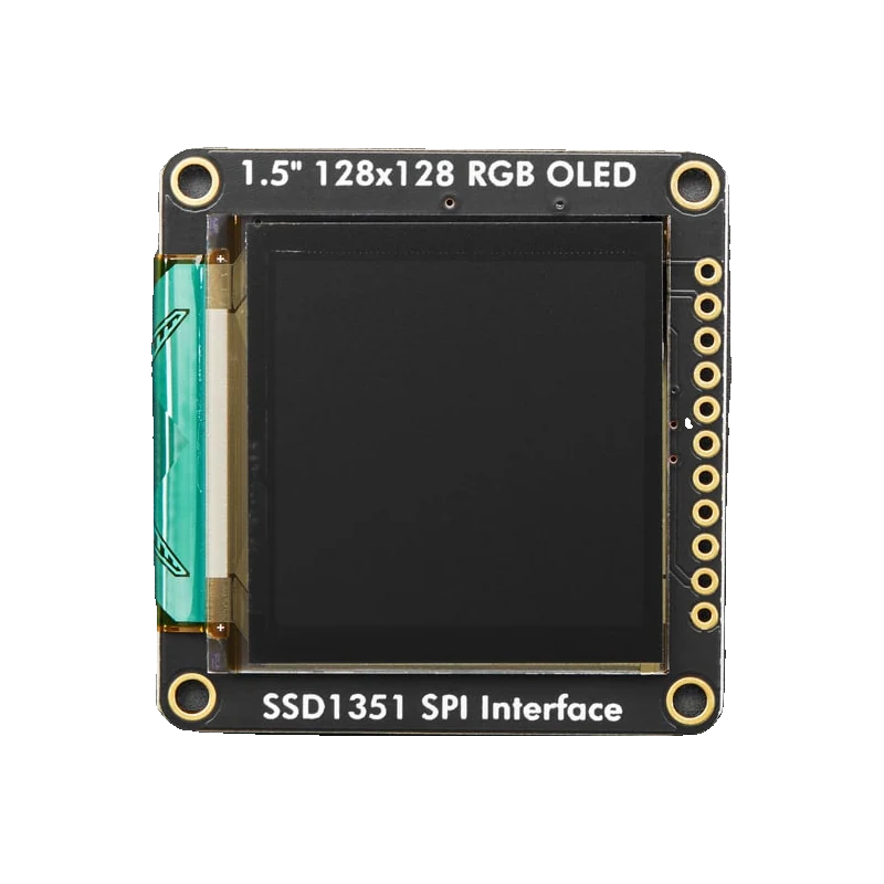
Adafruit's 1.5-inch colour OLED shows 128 × 128 pixels in 16-bit colour from Solomon Systech's SSD1351, a controller that supports up to 262k colours with its own 128 × 128 × 18-bit frame memory (SSD1351 Rev 1.3, p. 7). The board adds a boost converter for the panel's high voltage, logic level shifting for 3 V to 5 V power and logic, and a microSD holder, and draws about 30 mA in typical use (Adafruit product 1431). It talks write-only SPI with OLEDCS, DC and RESET, driven by the Adafruit_SSD1351 library.
Each of the 128 × 128 pixels is made of red, green and blue organic LEDs, so there is no backlight: black is truly black, colours are vivid and the screen reads well from any angle. The SSD1351 keeps the whole image in its own memory and accepts 65k-colour (5-6-5) or 262k-colour (6-6-6) pixels (SSD1351 Rev 1.3, p. 7), so the microcontroller only sends what changes.
The bare SSD1351 needs a logic supply of 1.65 V up to VCI, a VCI of 2.4 V to 3.5 V and a panel supply of 10 V to 18 V (p. 7). Adafruit's board makes all of that from Vin: a regulator, a small boost converter for the panel, and level shifters so Vin and the logic can both be 3 V to 5 V (Adafruit product 1431). The pins are Vin, 3Vo, GND, SCLK, MOSI, MISO, OLEDCS, SDCS, DC, RESET and CD, with an 18-pin EYESPI connector on newer boards.
Current depends on how many pixels are lit; Adafruit measures around 30 mA in practice, not counting the SD card (product 1431). Like any OLED, pixels lit for long periods dim over time, Adafruit's figure being after about 1000 hours, so screen savers and dark backgrounds extend its life.
SSD1351 OLED 1.5" pinout
| Pin | Function | Type |
|---|---|---|
| Vin | Supply3 V to 5 V | power in |
| 3Vo | 3.3 V regulator output | power out |
| GND | Ground | power in |
| SCLK | SPI SCK3 V to 5 V | input |
| MOSI | SPI MOSI3 V to 5 V | input |
| MISO | SPI MISO (SD card only) | output |
| OLEDCS | OLED CS (active low)3 V to 5 V | input |
| SDCS | SD card CS (active low)3 V to 5 V | input |
| DC | Data / command select3 V to 5 V | input |
| RESET | OLED reset (active low)3 V to 5 V | input |
| CD | SD card detect | output |
How to wire the SSD1351 OLED 1.5"
Pin by pin, for the board you have.
| SSD1351 OLED 1.5" | Arduino Uno | Note |
|---|---|---|
| Vin | 5V | |
| GND | GND | |
| SCLK | D13 | |
| MOSI | D11 | |
| OLEDCS | D10 | |
| DC | D9 | |
| RESET | D8 |
| SSD1351 OLED 1.5" | ESP32 DevKit V1 | Note |
|---|---|---|
| Vin | 3V3 | |
| GND | GND | |
| SCLK | GPIO18 (D18) | |
| MOSI | GPIO23 (D23) | |
| OLEDCS | GPIO5 (D5) | |
| DC | GPIO16 (RX2) | |
| RESET | GPIO17 (TX2) |
| SSD1351 OLED 1.5" | Raspberry Pi Pico | Note |
|---|---|---|
| Vin | 3V3(OUT) | |
| GND | GND | |
| SCLK | GP18 | |
| MOSI | GP19 | |
| OLEDCS | GP17 | |
| DC | GP21 | |
| RESET | GP20 |
SSD1351 OLED 1.5" code
Every example here compiles for its board.
// SSD1351 OLED 1.5" on Arduino Uno: wiring and a free simulation at https://www.tinkered.ai/components/ssd1351-oled-1-5
// Adafruit 1.5" SSD1351 128x128 colour OLED on an Arduino Uno: SCLK D13, MOSI D11, OLEDCS D10, DC D9, RESET D8
#include <SPI.h>
#include <Adafruit_GFX.h>
#include <Adafruit_SSD1351.h>

const int OLED_CS = 10;
const int OLED_DC = 9;
const int OLED_RST = 8;
const uint16_t BLACK = 0x0000;
const uint16_t WHITE = 0xFFFF;
const uint16_t CYAN = 0x07FF;
const uint16_t MAGENTA = 0xF81F;

Adafruit_SSD1351 oled(128, 128, &SPI, OLED_CS, OLED_DC, OLED_RST);

void setup() {
  Serial.begin(115200);
  oled.begin();
  oled.fillScreen(BLACK);
  oled.fillCircle(64, 40, 28, MAGENTA);
  oled.setTextColor(CYAN);
  oled.setTextSize(2);
  oled.setCursor(10, 78);
  oled.print(F("SSD1351"));
  oled.setTextColor(WHITE, BLACK);
  Serial.println(F("OLED ready"));
}

void loop() {
  static unsigned long seconds = 0;
  oled.setTextSize(2);
  oled.setCursor(10, 104);
  oled.print(seconds);
  oled.print(F(" s "));
  Serial.print(F("Uptime: "));
  Serial.println(seconds);
  seconds++;
  delay(1000);
}
// SSD1351 OLED 1.5" on ESP32 DevKit V1: wiring and a free simulation at https://www.tinkered.ai/components/ssd1351-oled-1-5
// Adafruit 1.5" SSD1351 128x128 colour OLED on an ESP32 DevKit V1: SCLK GPIO18, MOSI GPIO23, OLEDCS GPIO5, DC GPIO16, RESET GPIO17
#include <SPI.h>
#include <Adafruit_GFX.h>
#include <Adafruit_SSD1351.h>

const int OLED_CS = 5;
const int OLED_DC = 16;
const int OLED_RST = 17;
const uint16_t BLACK = 0x0000;
const uint16_t WHITE = 0xFFFF;
const uint16_t CYAN = 0x07FF;
const uint16_t MAGENTA = 0xF81F;

Adafruit_SSD1351 oled(128, 128, &SPI, OLED_CS, OLED_DC, OLED_RST);

void setup() {
  Serial.begin(115200);
  oled.begin();
  oled.fillScreen(BLACK);
  oled.fillCircle(64, 40, 28, MAGENTA);
  oled.setTextColor(CYAN);
  oled.setTextSize(2);
  oled.setCursor(10, 78);
  oled.print("SSD1351");
  oled.setTextColor(WHITE, BLACK);
  Serial.println("OLED ready");
}

void loop() {
  static unsigned long seconds = 0;
  oled.setTextSize(2);
  oled.setCursor(10, 104);
  oled.printf("%lu s ", seconds);
  Serial.printf("Uptime: %lu s\n", seconds);
  seconds++;
  delay(1000);
}
// SSD1351 OLED 1.5" on Raspberry Pi Pico: wiring and a free simulation at https://www.tinkered.ai/components/ssd1351-oled-1-5
// Adafruit 1.5" SSD1351 128x128 colour OLED on a Raspberry Pi Pico (arduino-pico): SCLK GP18, MOSI GP19, OLEDCS GP17, DC GP21, RESET GP20
#include <SPI.h>
#include <Adafruit_GFX.h>
#include <Adafruit_SSD1351.h>

const int OLED_CS = 17;
const int OLED_DC = 21;
const int OLED_RST = 20;
const uint16_t BLACK = 0x0000;
const uint16_t WHITE = 0xFFFF;
const uint16_t CYAN = 0x07FF;
const uint16_t MAGENTA = 0xF81F;

Adafruit_SSD1351 oled(128, 128, &SPI, OLED_CS, OLED_DC, OLED_RST);

void setup() {
  Serial.begin(115200);
  SPI.setSCK(18);
  SPI.setTX(19);
  oled.begin();
  oled.fillScreen(BLACK);
  oled.fillCircle(64, 40, 28, MAGENTA);
  oled.setTextColor(CYAN);
  oled.setTextSize(2);
  oled.setCursor(10, 78);
  oled.print("SSD1351");
  oled.setTextColor(WHITE, BLACK);
  Serial.println("OLED ready");
}

void loop() {
  static unsigned long seconds = 0;
  oled.setTextSize(2);
  oled.setCursor(10, 104);
  oled.print(seconds);
  oled.print(" s ");
  Serial.print("Uptime: ");
  Serial.println(seconds);
  seconds++;
  delay(1000);
}
Before you wire it
- Power Vin from 3 V to 5 V; the board makes the panel's high voltage itself (Adafruit product 1431).
- Pass the width and height (128, 128) and the SPI bus to the constructor, as the library's current constructors expect.
- Give the OLED and the SD card separate CS pins when both are used.
- Blank or dim the screen when idle: OLED pixels age with use.
- Never leave the same bright image on for days; static pixels dim before the rest.
- Never try to read from the display: SPI on the SSD1351 is write-only, MISO serves only the SD card.
- Never feed the 3Vo pin from outside: it is the regulator's output.
- The SSD1351 needs 10 V to 18 V for the panel (SSD1351 Rev 1.3, p. 7); the board's boost converter makes it from Vin, so no extra supply is wired.
- In 4-wire SPI the SSD1351 is specified to a 50 ns clock cycle, 20 MHz (p. 53); begin() without an argument uses the library's default speed for the board.
- Current rises with the number and brightness of lit pixels; dark themes use far less than a white background.
- RESET can be tied to the board's reset, but letting the library drive it gives a cleaner start.
- Use Adafruit_ImageReader with the SD library to draw BMP images from the card.
Specifications
- Resolution and colour
- 128 × 128 RGB pixels, 16-bit colour on this board; controller supports 65k and 262k coloursAdafruit product 1431 page; SSD1351 Rev 1.3, p. 7
- Controller
- Solomon Systech SSD1351 with 128 × 128 × 18-bit display RAMSSD1351 Rev 1.3, p. 7
- Controller supplies
- VDDIO 1.65 V to VCI, VCI 2.4 V to 3.5 V, VCC (panel) 10 V to 18 VSSD1351 Rev 1.3, p. 7
- SPI clock
- 50 ns minimum clock cycle (20 MHz) in 4-wire SPISSD1351 Rev 1.3, Table 13-4, p. 53
- Board power and logic
- 3.3 V to 5 V, level shifted; on-board boost converter for the OLED panelAdafruit product 1431 page
- Current
- About 30 mA in typical use, depending on lit pixels (SD card extra)Adafruit product 1431 page
- Size
- 43.17 × 42 × 5.42 mmAdafruit product 1431 page
From the Solomon Systech SSD1351 Advance Information Rev 1.3, published by Solomon Systech (SSD1351), board by Adafruit.
Common mistakes
Old constructor arguments
Examples written for older library versions pass only the pins. Current Adafruit_SSD1351 versions expect width and height first, as in oled(128, 128, &SPI, CS, DC, RST); mixing the forms gives a blank or wrongly sized screen.
Burn-in from a static screen
A clock face or logo shown for months dims those pixels. Adafruit notes OLED pixels start to dim after about 1000 hours on (product 1431); move content or blank the screen.
Card and display on the same CS
OLEDCS and SDCS must be separate pins; with SDCS left floating low, the card can corrupt display transfers.
SSD1351 OLED 1.5" questions
Is the Adafruit SSD1351 OLED 5 V compatible?
Yes. Adafruit's breakout accepts 3 V to 5 V power and logic thanks to on-board level shifting (product 1431). The bare SSD1351's logic supply tops out at VCI, 3.5 V maximum (SSD1351 Rev 1.3, p. 7), so bare modules from other sellers may need 3.3 V logic.
How much current does the 1.5-inch colour OLED draw?
About 30 mA in typical use according to Adafruit, but it depends on how many pixels are lit and how bright they are (product 1431). A mostly black screen draws much less than a white one.
Which library drives the SSD1351?
Adafruit_SSD1351 with Adafruit GFX. Construct it with Adafruit_SSD1351(128, 128, &SPI, cs, dc, rst) and call begin().
SSD1351 OLED or ST7789 TFT?
The OLED has true blacks, wider viewing angles and no backlight, but is smaller and can burn in. The ST7789 IPS TFT gives more pixels for the money and never burns in.
Can it show photos?
Yes: store 128 × 128 BMP files on the microSD card and draw them with Adafruit_ImageReader. The panel shows 16-bit colour (product 1431).
Build something with the SSD1351 OLED 1.5"
- Build this
Colour mini dashboard
Bars and gauges for several sensors on a vivid OLED.
- Build this
Pixel art viewer
Cycle 128 × 128 images from the microSD card.
This page as plain Markdown, for ChatGPT, Claude or your own agent. /components/ssd1351-oled-1-5.md