1.28" Round TFT Display (GC9A01)
A 1.28 inch round 240x240 IPS color display on a GC9A01 controller, driven over 4-wire SPI: the screen behind most DIY watch faces and gauges.
- ControllerGalaxycore GC9A01, 240RGB x 240 a-Si TFT driver
- Frame memory129,600 bytes on chip
- Pixel formats12-bit (4K), 16-bit RGB 565 (65K), 18-bit (262K)
- Interface4-line SPI: CSX, SCL, SDA, D/CX (D/CX low = command)
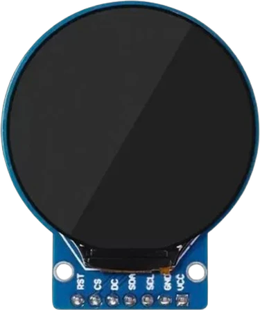
The 1.28 inch round TFT is a 240x240 IPS color display driven by Galaxycore's GC9A01, a controller with 129,600 bytes of on-chip frame memory and a 4-line SPI interface (GC9A01 datasheet V1.0, pp. 6, 28). Wire SCL to the board's SPI clock, SDA to MOSI, and CS, DC and RST to any three GPIOs, with VCC on 3.3 V or 5 V as the module allows. The controller's logic runs at 1.65 V to 3.3 V and its inputs are rated to IOVCC + 0.3 V (pp. 182, 183), so 3.3 V boards connect directly and a 5 V board needs level shifting unless the module provides it.
This module is a round 1.28 inch IPS TFT with a resolution of 240 by 240 pixels, driven by the GC9A01 from Galaxycore. The controller holds the whole picture in 129,600 bytes of internal display RAM, so the microcontroller only sends pixels that change, and the panel keeps showing the last frame without any refresh from the host (GC9A01 datasheet V1.0, pp. 6, 7). Only the inscribed circle of the square pixel grid is behind glass: draw around the centre at (120, 120) and keep content within a radius of 120 pixels.
The seven-pin version talks over 4-line SPI: CS selects the chip, SCL is the clock, SDA carries data into the display, and DC (the datasheet's D/CX) tells it whether each byte is a command (low) or data (high) (pp. 11, 29). RST resets the controller. Despite the I2C-style labels on the silkscreen, SDA and SCL are SPI lines and must go to the board's MOSI and SCK. The backlight is wired on and there is no MISO pin, so the display is write-only.
The GC9A01 accepts 12-bit, 16-bit (RGB 565, 65K colors) and 18-bit pixel formats (p. 46); Arduino libraries such as Adafruit_GC9A01A with Adafruit_GFX use 16-bit color. The chip's analog supply runs from 2.5 V to 3.3 V and its logic supply from 1.65 V to 3.3 V (p. 183), so modules carry their own regulator to accept 3.3 V or 5 V on VCC. Waveshare's version of the module lists a 32.4 mm display diameter and 0.135 mm pixel pitch (Waveshare 1.28inch LCD Module wiki).
1.28" Round TFT Display (GC9A01) pinout
| Pin | Function | Type |
|---|---|---|
| RST | Digital | input |
| CS | SPI chip select, active low | input |
| DC | SPI data/command select | input |
| SDA | SPI MOSI | input |
| SCL | SPI SCK | input |
| GND | GND | power in |
| VCC | VCC (3.3-5V)3.3 V (max 5 V) | power in |
How to wire the 1.28" Round TFT Display (GC9A01)
Pin by pin, for the board you have.
| 1.28" Round TFT Display (GC9A01) | Arduino Uno | Note |
|---|---|---|
| VCC | 5V | |
| GND | GND | |
| CS | D10 | |
| DC | D2 | |
| RST | D3 | |
| SDA | D11 | |
| SCL | D13 |
- Its inputs are rated to its 3.3 V I/O supply plus 0.3 V: put a level shifter between this board's 5 V pins and the display.
| 1.28" Round TFT Display (GC9A01) | ESP32 DevKit V1 | Note |
|---|---|---|
| VCC | 3V3 | |
| GND | GND | |
| CS | GPIO5 (D5) | |
| DC | GPIO13 (D13) | |
| RST | GPIO14 (D14) | |
| SDA | GPIO23 (D23) | |
| SCL | GPIO18 (D18) |
| 1.28" Round TFT Display (GC9A01) | Raspberry Pi Pico | Note |
|---|---|---|
| VCC | 3V3 | |
| GND | GND | |
| CS | GP17 | |
| DC | GP0 | |
| RST | GP1 | |
| SDA | GP19 | |
| SCL | GP18 |
1.28" Round TFT Display (GC9A01) code
Every example here compiles for its board.
// 1.28" Round TFT Display (GC9A01) on Arduino Uno: wiring and a free simulation at https://www.tinkered.ai/components/gc9a01-round-tft
#include <Adafruit_GFX.h>
#include <Adafruit_GC9A01A.h>

#define TFT_CS 10   // disp_1:CS  -> SS
#define TFT_DC 2    // disp_1:DC  -> D2
#define TFT_RST 3   // disp_1:RST -> D3

// Hardware SPI: SDA->MOSI and SCL->SCK are the fixed SPI pins (D11/D13 on Uno).
Adafruit_GC9A01A tft(TFT_CS, TFT_DC, TFT_RST);

void setup() {
  tft.begin();
  tft.fillScreen(GC9A01A_BLACK);

  // The glass is a circle: centre is (120, 120), usable radius 120.
  tft.drawCircle(120, 120, 118, GC9A01A_WHITE);
  tft.fillCircle(120, 120, 60, GC9A01A_BLUE);

  tft.setTextColor(GC9A01A_WHITE);
  tft.setTextSize(3);
  // Centre the text rather than starting at a corner, which is off-glass.
  tft.setCursor(60, 108);
  tft.println("ROUND");
}

void loop() {}
// 1.28" Round TFT Display (GC9A01) on STM32 Blue Pill (F103C8): wiring and a free simulation at https://www.tinkered.ai/components/gc9a01-round-tft
#include <Arduino.h>
#include <Arduino_GFX_Library.h>
Arduino_DataBus *bus = new Arduino_HWSPI(PB0 /* DC */, PA4 /* CS */);
Arduino_GFX *tft = new Arduino_GC9A01(bus, PB1 /* RST */, 0 /* rotation */, true /* IPS */);

void setup() {
  tft->begin();
  tft->fillScreen(RGB565_BLACK);
  tft->fillCircle(120, 120, 60, RGB565_BLUE);
}
void loop() {}
Before you wire it
- Wire the display SPI bus to the MCU's hardware SPI pins: SCL → SCK and SDA → MOSI. The silkscreen uses I2C-style names, but this is SPI: SCL is the clock and SDA is MOSI.
- CS (chip-select) → the SPI SS pin or any free GPIO; pass it as TFT_CS.
- DC (data/command, a.k.a. RS) → any free GPIO; pass it as TFT_DC. This is the key line: LOW selects a command byte, HIGH selects data/pixel bytes.
- RST → any free GPIO; pass it as TFT_RST.
- VCC → 3.3V or 5V, GND → GND.
- The drawable area is a CIRCLE. The controller's memory is a 240x240 square, but only the inscribed disc is behind glass: exactly as on real hardware. Centre content on (120, 120) and keep it within radius 120. Anything drawn into the square's corners is written but never visible.
- No bit-banged / software SPI.
- No MISO and NO BLK/backlight wiring. This seven-pin module has neither pin: the GC9A01 is write-only over SPI here, and the backlight is hardwired on. Do not invent those pins from the eight-pin variants.
- No TFT_eSPI, LovyanGFX, Arduino_GFX or vendor demo code: use Adafruit_GC9A01A + Adafruit_GFX. See the notes for the two independent reasons this matters here. The one exception is the UNO R4 (below).
- Wire SCL to the board's hardware SPI clock and SDA to MOSI (D13 and D11 on an Uno, GPIO18 and GPIO23 on a classic ESP32). These are SPI signals despite their names.
- CS, DC and RST can use any free GPIOs; pass them to the library constructor. DC low marks a command byte and DC high marks data (GC9A01 datasheet, p. 29), so a miswired DC gives a blank or garbled screen.
- The GC9A01's logic inputs are rated to IOVCC + 0.3 V with IOVCC at 3.3 V at most (datasheet, pp. 182, 183). On 3.3 V boards (ESP32, Pico, STM32) wire directly. On a 5 V Uno or Nano, check whether your module has a level shifter; if it does not, drive CS, DC, RST, SDA and SCL through a 74HC4050 or similar level shifter.
- Power VCC from 3.3 V or 5 V as your module's regulator allows, and share ground with the board. Waveshare quotes 31.2 mA maximum at 3.3 V for its module.
- Only the inscribed disc is visible. Centre graphics on (120, 120); text started at the top-left corner lands off the glass.
Specifications
- Controller
- Galaxycore GC9A01, 240RGB x 240 a-Si TFT driverGC9A01 datasheet V1.0 (Preliminary), p. 1
- Frame memory
- 129,600 bytes on chipGC9A01 datasheet V1.0, pp. 6, 7
- Pixel formats
- 12-bit (4K), 16-bit RGB 565 (65K), 18-bit (262K)GC9A01 datasheet V1.0, pp. 7, 46
- Interface
- 4-line SPI: CSX, SCL, SDA, D/CX (D/CX low = command)GC9A01 datasheet V1.0, pp. 11, 28, 29
- Chip supply
- VCI 2.5 V to 3.3 V (analog), IOVCC 1.65 V to 3.3 V (logic)GC9A01 datasheet V1.0, p. 183
- Logic input limit
- -0.3 V to IOVCC + 0.3 V (absolute maximum)GC9A01 datasheet V1.0, p. 182
- SPI write timing
- 10 ns minimum serial clock cycle for writes, 150 ns for readsGC9A01 datasheet V1.0, p. 190
- Module supply
- 3.3 V or 5 V (Waveshare module)Waveshare 1.28inch LCD Module wiki
- Display area
- 32.4 mm diameter, 0.135 x 0.135 mm pixel pitch (Waveshare module)Waveshare 1.28inch LCD Module wiki
- Supply voltage
- 3.3 V
- Maximum supply voltage
- 5 V
- SPI mode
- 0
- Dimensions
- 38.05 × 45.5 × 5.51 mm
- Weight
- 8 g
From the Teyleten Robot / generic GC9A01 breakout's datasheet, published by Teyleten Robot / generic GC9A01 breakout.
Common mistakes
Wiring SDA and SCL to the I2C pins
The silkscreen borrows I2C names, but the GC9A01 module is a 4-line SPI device (datasheet, p. 28). SDA goes to MOSI and SCL to SCK; on an Uno that is D11 and D13, not A4 and A5.
Drawing in the corners
The controller's memory is a 240x240 square, but the glass is a circle. Anything drawn near the corners is written and never seen, which makes a correct sketch look broken. Lay out content around the centre.
Driving 3.3 V logic with 5 V signals
The chip's inputs are rated to IOVCC + 0.3 V, and IOVCC tops out at 3.3 V (datasheet, pp. 182, 183). A module without a level shifter is stressed by a 5 V Uno's SPI lines; use a 3.3 V board or a level shifter.
Swapping DC and CS, or leaving RST floating
DC selects command or data and CS frames each transfer. Swapped, the display receives nonsense and stays black. Give RST a GPIO and pass it to the library, or hold it high, so the controller is not held in reset.
Mixing libraries with different orientation settings
GC9A01 libraries disagree on the orientation register, so code ported from one library to another can draw mirrored. Pick one library, Adafruit_GC9A01A with Adafruit_GFX for example, and use its setRotation().
1.28" Round TFT Display (GC9A01) questions
How do I connect the GC9A01 round display to an ESP32?
Wire VCC to 3V3, GND to GND, SCL to GPIO18 (SCK), SDA to GPIO23 (MOSI), and CS, DC and RST to three free GPIOs such as 5, 13 and 14. The ESP32 is a 3.3 V board, which matches the GC9A01's 1.65 V to 3.3 V logic supply (GC9A01 datasheet V1.0, p. 183). Then use Adafruit_GC9A01A with your three pin numbers.
Can I use the GC9A01 with a 5 V Arduino Uno?
The module's VCC takes 5 V on boards with a regulator (Waveshare lists 3.3 V or 5 V), but the controller's logic inputs are rated to IOVCC + 0.3 V with IOVCC at 3.3 V maximum (datasheet, pp. 182, 183). Unless your module has a level shifter, put one between the Uno's D10, D11, D13 and the CS, DC, RST, SDA and SCL pins.
Why is my GC9A01 display blank or white?
A lit but blank screen means the backlight has power and the controller has not been initialised. Check that SDA goes to MOSI and SCL to SCK (not the I2C pins), that DC and CS match the pins in your constructor, and that RST is wired or held high. DC must be low for commands and high for data (datasheet, p. 29).
Is the GC9A01 display SPI or I2C?
SPI. The seven-pin module uses the GC9A01's 4-line serial interface with CS, SCL, SDA and D/CX (datasheet, p. 28); the SDA and SCL labels are only names for the SPI data and clock lines.
What is the resolution of the 1.28 inch round display?
240 by 240 pixels, the GC9A01's full 240RGB x 240 resolution (datasheet, p. 1). Only the inscribed circle is visible, so the usable area is a disc of 120 pixels radius around (120, 120).
How many colors does the GC9A01 show?
Up to 262K colors in its 18-bit pixel format, or 65K in 16-bit RGB 565, which most Arduino libraries use (datasheet, pp. 7, 46).
Build something with the 1.28" Round TFT Display (GC9A01)
- Build this
Smartwatch face
Pair it with an ESP32 and an RTC to draw an analog watch face with hands, ticks and the date in the round frame.
- Build this
Car or bike gauge
Draw a needle gauge for speed, RPM or battery voltage, the round glass doing the work of a real instrument dial.
- Build this
Animated eyes
Two round displays side by side make expressive robot or Halloween eyes that blink and look around.
- Build this
Weather or air-quality dial
Show temperature, humidity or CO2 as an arc around the edge with the value in the middle.
This page as plain Markdown, for ChatGPT, Claude or your own agent. /components/gc9a01-round-tft.md