4.0" TFT Touch Display (ST7796S)
A 4.0 inch 480x320 color TFT on a Sitronix ST7796S controller, with XPT2046 resistive touch and a microSD slot, all on one SPI bus.
- Controller resolution320RGB x 480, used as 480 x 320 landscape
- Frame memory320 x 480 x 18 bits = 2,764,800 bits on chip
- Pixel formats16-bit RGB 565 (65K), 18-bit (262K), 24-bit (16M)
- Chip supplyVDDI 1.65 V to 3.3 V, VDD and VDDA 2.5 V to 3.3 V
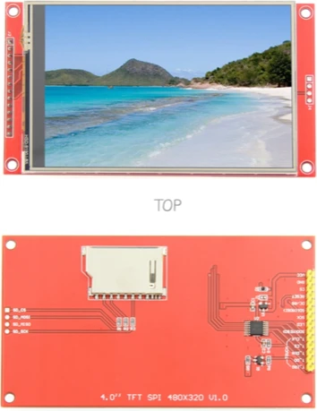
The 4.0 inch ST7796S module is a 480x320 color TFT driven over 4-wire SPI, with an XPT2046 resistive touch controller and a microSD slot on the same board, and it takes 3.3 V to 5 V on VCC (LCDWiki MSP4021 page). Wire SCK, MOSI and MISO to the board's hardware SPI pins, give the display, touch and SD card one chip select each, and tie LED high to light the backlight. The ST7796S itself runs its I/O at 1.65 V to 3.3 V with inputs rated to VDDI + 0.5 V (Sitronix ST7796S datasheet V1.0, pp. 9, 46), so 3.3 V boards connect directly.
This 4.0 inch module (LCDWiki sells it as the MSP4021 with touch and the MSP4020 without) puts a 480x320 TFT panel driven by Sitronix's ST7796S, an XPT2046 resistive touch controller and a microSD socket on one PCB. Its 14-pin header carries power, the display's SPI and control lines, the backlight enable and the touch controller's own SPI pins; the SD card has a separate 4-pin header on the opposite edge (LCDWiki MSP4021 page).
The ST7796S is a single-chip controller for 320RGB x 480 panels with a full frame buffer of 320 x 480 x 18 bits on chip (Sitronix ST7796S datasheet V1.0, p. 8). It accepts 16-bit RGB 565 (65K colors), 18-bit (262K) and 24-bit pixels, and the panel is natively portrait, so libraries rotate it to the 480x320 landscape the module is sold as. Over 4-line SPI the DC pin (the datasheet's D/CX) marks each byte as a command when low or data when high (p. 42), and the write clock cycle can be as short as 66 ns (p. 54).
The three devices share SCK, MOSI and MISO and differ only by their chip-select lines: CS for the display, T_CS for touch and SD_CS for the card. The module takes 3.3 V to 5 V on VCC through its regulator (LCDWiki), while the ST7796S's own I/O supply is 1.65 V to 3.3 V (datasheet, p. 9), so a 3.3 V board such as an ESP32 or Pico is the natural partner; LCDWiki's page does not state 5 V logic tolerance.
4.0" TFT Touch Display (ST7796S) pinout
| Pin | Function | Type |
|---|---|---|
| VCC | VCC (3.3-5V)3.3–5 V | power in |
| GND | GND | power in |
| CS | SPI display chip select | input |
| RESET | Digital | input |
| DC | SPI data/command select | input |
| MOSI | SPI MOSI | input |
| SCK | SPI SCK | input |
| LED | Digital | input |
| MISO | SPI MISO3.3 V | output |
| T_CLK | SPI touch SCK | input |
| T_CS | SPI touch chip select | input |
| T_DIN | SPI touch MOSI | input |
| T_DO | SPI touch MISO | output |
| T_IRQ | Digital | output |
| SD_CS | SPI microSD chip select | input |
| SD_MOSI | SPI microSD MOSI | input |
| SD_MISO | SPI microSD MISO | output |
| SD_SCK | SPI microSD SCK | input |
How to wire the 4.0" TFT Touch Display (ST7796S)
Pin by pin, for the board you have.
| 4.0" TFT Touch Display (ST7796S) | Arduino Uno | Note |
|---|---|---|
| VCC | 5V | |
| GND | GND | |
| LED | 3V3 | |
| CS | D2 | |
| RESET | D3 | |
| DC | D4 | |
| MOSI | D11 | |
| MISO | D12 | |
| SCK | D13 | |
| T_CS | D5 | |
| T_CLK | D13 | |
| T_DIN | D11 | |
| T_DO | D12 | |
| SD_CS | D6 | |
| SD_SCK | D13 | |
| SD_MOSI | D11 | |
| SD_MISO | D12 |
- Its inputs are rated to its 3.3 V I/O supply plus 0.5 V: put a level shifter between this board's 5 V pins and the display.
| 4.0" TFT Touch Display (ST7796S) | ESP32 DevKit V1 | Note |
|---|---|---|
| VCC | 3V3 | |
| GND | GND | |
| LED | 3V3 | |
| CS | GPIO13 (D13) | |
| RESET | GPIO14 (D14) | |
| DC | GPIO27 (D27) | |
| MOSI | GPIO23 (D23) | |
| MISO | GPIO19 (D19) | |
| SCK | GPIO18 (D18) | |
| T_CS | GPIO26 (D26) | |
| T_CLK | GPIO18 (D18) | |
| T_DIN | GPIO23 (D23) | |
| T_DO | GPIO19 (D19) | |
| SD_CS | GPIO25 (D25) | |
| SD_SCK | GPIO18 (D18) | |
| SD_MOSI | GPIO23 (D23) | |
| SD_MISO | GPIO19 (D19) |
| 4.0" TFT Touch Display (ST7796S) | Raspberry Pi Pico | Note |
|---|---|---|
| VCC | 3V3 | |
| GND | GND | |
| LED | 3V3 | |
| CS | GP0 | |
| RESET | GP1 | |
| DC | GP2 | |
| MOSI | GP19 | |
| MISO | GP16 | |
| SCK | GP18 | |
| T_CS | GP3 | |
| T_CLK | GP18 | |
| T_DIN | GP19 | |
| T_DO | GP16 | |
| SD_CS | GP4 | |
| SD_SCK | GP18 | |
| SD_MOSI | GP19 | |
| SD_MISO | GP16 |
4.0" TFT Touch Display (ST7796S) code
Every example here compiles for its board.
// 4.0" TFT Touch Display (ST7796S) on Arduino Uno: wiring and a free simulation at https://www.tinkered.ai/components/st7796s-tft-4
#include <Adafruit_GFX.h>
#include <Adafruit_ST7796S.h>
#include <XPT2046_Touchscreen.h>
#include <SPI.h>
#include <SD.h>

#define TFT_CS    2
#define TFT_DC    4
#define TFT_RST   3
#define TOUCH_CS  5
#define SD_CS     6

Adafruit_ST7796S tft(TFT_CS, TFT_DC, TFT_RST);
XPT2046_Touchscreen ts(TOUCH_CS);

void setup() {
  Serial.begin(9600);
  tft.init(320, 480);             // Adafruit_ST7796S: init(), its begin() is protected
  tft.setRotation(1);              // 480x320 landscape
  tft.fillScreen(ST77XX_BLACK);
  tft.setCursor(10, 10);
  tft.setTextColor(ST77XX_WHITE);
  tft.print("Hello");

  ts.begin();

  if (SD.begin(SD_CS)) {
    File f = SD.open("/README.TXT");
    if (f) { while (f.available()) Serial.write(f.read()); f.close(); }
  }
}

void loop() {
  if (ts.touched()) {
    TS_Point p = ts.getPoint();    // raw 12-bit counts, needs calibrating
    tft.fillCircle(map(p.x, 200, 3900, 0, 479),
                   map(p.y, 200, 3900, 0, 319), 3, ST77XX_RED);
  }
}
// 4.0" TFT Touch Display (ST7796S) on STM32 Blue Pill (F103C8): wiring and a free simulation at https://www.tinkered.ai/components/st7796s-tft-4
#include <Arduino.h>
#include <SPI.h>
#include <Arduino_GFX_Library.h>
#include <XPT2046_Touchscreen.h>
Arduino_DataBus *bus = new Arduino_HWSPI(PB0 /* DC */, PA4 /* CS */);
Arduino_GFX *tft = new Arduino_ST7796(bus, PB1 /* RST */, 0 /* rotation */, false /* IPS */, 320, 480);
XPT2046_Touchscreen ts(PB10 /* T_CS */, PB11 /* T_IRQ */);   // the touch shares the SPI bus

void setup() {
  tft->begin();
  ts.begin();
  tft->fillScreen(RGB565_BLACK);
}
void loop() {
  if (ts.touched()) { TS_Point p = ts.getPoint(); tft->fillCircle(p.x * 320 / 4096, p.y * 480 / 4096, 3, RGB565_WHITE); }
}
Before you wire it
- This is THREE SPI devices on one bus, each with its own chip select: the ST7796S display (CS), an XPT2046 touch controller (T_CS), and a microSD slot (SD_CS). They share MOSI / MISO / SCK. Never give two of them the same CS.
- Two separate headers. The 14-pin J2 carries VCC, GND, CS, RESET, DC/RS, SDI(MOSI), SCK, LED, SDO(MISO), T_CLK, T_CS, T_DIN, T_DO, T_IRQ. The SD pins (SD_CS, SD_MOSI, SD_MISO, SD_SCK) are on a SEPARATE 4-pin header on the opposite edge of the board.
- Only J2 plugs into the breadboard. The PCB is 108mm long against a 25mm-wide hole field, so it is mounted on the board's outer column and the rest of it overhangs into open space. The microSD header ends up ~104mm away, off the board, and is wired with direct jumpers: never given breadboard holes.
- The touch and SD headers duplicate the SPI bus. Wire T_CLK/T_DIN/T_DO and SD_SCK/SD_MOSI/SD_MISO to the same SCK/MOSI/MISO pins as the display; only the three chip selects need their own GPIOs.
- LED is the backlight enable, active HIGH.
- 3.3V logic.
- Do not use TFT_eSPI or LovyanGFX. DMA-pushing libraries send far larger transactions and render sheared and mis-coloured.
- Do not put the display on a second SPI bus.
- Do not share one chip select between the display, touch and SD.
- Put the display, touch and SD card on the same hardware SPI pins (SCK, MOSI, MISO) and give each its own chip select: CS, T_CS and SD_CS. Two devices on one chip select fight over MISO.
- LED enables the backlight when high. LCDWiki suggests tying it to 3.3 V for an always-on backlight, or drive it from a GPIO (or PWM through a transistor) to switch it.
- The ST7796S's I/O runs at 1.65 V to 3.3 V and its inputs are rated to VDDI + 0.5 V (Sitronix datasheet, pp. 9, 46). On a 3.3 V board wire directly. On a 5 V Uno or Mega, check your module for a level shifter, and if it has none, shift CS, RESET, DC, MOSI, SCK, T_CS, T_CLK, T_DIN and SD_CS down to 3.3 V.
- SDO (MISO) only matters for reading back from the display; LCDWiki notes it can be left unconnected if you never read. Touch and SD still need MISO.
- T_IRQ goes low while the screen is touched (LCDWiki), so wire it to an input to skip polling the XPT2046 when nobody is touching it.
Specifications
- Controller resolution
- 320RGB x 480, used as 480 x 320 landscapeSitronix ST7796S datasheet V1.0, p. 8
- Frame memory
- 320 x 480 x 18 bits = 2,764,800 bits on chipSitronix ST7796S datasheet V1.0, p. 8
- Pixel formats
- 16-bit RGB 565 (65K), 18-bit (262K), 24-bit (16M)Sitronix ST7796S datasheet V1.0, p. 8
- Chip supply
- VDDI 1.65 V to 3.3 V, VDD and VDDA 2.5 V to 3.3 VSitronix ST7796S datasheet V1.0, p. 9
- Logic input limit
- Up to VDDI + 0.5 V (absolute)Sitronix ST7796S datasheet V1.0, p. 46
- SPI write clock
- 66 ns minimum cycle; D/CX low = command, high = dataSitronix ST7796S datasheet V1.0, pp. 42, 54
- Module supply
- 3.3 V to 5 V on VCCLCDWiki 4.0inch SPI Module ST7796 (MSP4021)
- Module size
- PCB 61.74 x 108.04 mm, active area 55.68 x 83.52 mmLCDWiki 4.0inch SPI Module ST7796 (MSP4021)
- Touch
- Resistive, XPT2046 controller (MSP4021)LCDWiki 4.0inch SPI Module ST7796 (MSP4021)
- Header (J2)
- VCC, GND, CS, RESET, DC/RS, SDI(MOSI), SCK, LED, SDO(MISO), T_CLK, T_CS, T_DIN, T_DO, T_IRQLCDWiki 4.0inch SPI Module ST7796 (MSP4021)
- Supply voltage
- 3.3–5 V
- Maximum supply voltage
- 5.5 V
- Interface
- SPI
- SPI mode
- 0
- Dimensions
- 61.74 × 108.04 × 14.04 mm
- Weight
- 55 g
From the LCDWiki / generic ST7796S SPI module's datasheet, published by LCDWiki / generic ST7796S SPI module.
Common mistakes
Sharing one chip select
The display, touch controller and SD card all sit on one SPI bus. If two of them share a chip select, both answer at once and the screen, the touch readings or the card fail. Give CS, T_CS and SD_CS a GPIO each and keep the unused ones high.
Leaving LED unconnected
The LED pin enables the backlight when high (LCDWiki). Left floating, the controller can be running perfectly behind a dark panel. Tie it to 3.3 V or a GPIO set high.
Feeding 5 V logic to a 3.3 V controller
VCC accepts 5 V through the module's regulator, but the ST7796S's inputs are rated to VDDI + 0.5 V with VDDI at 3.3 V at most (Sitronix datasheet, pp. 9, 46). Use a 3.3 V board or level-shift the control and SPI lines from a 5 V Arduino.
Expecting landscape by default
The ST7796S is a 320 x 480 controller (datasheet, p. 8), so the panel starts in portrait. Call setRotation(1) for 480 x 320 landscape, and map touch coordinates after rotating.
Using raw touch values as pixels
The XPT2046 returns raw 12-bit counts, not screen coordinates. Calibrate by touching the corners and map() the readings to 0 to 479 and 0 to 319, or every touch lands in the wrong place.
4.0" TFT Touch Display (ST7796S) questions
How do I wire the 4.0 inch ST7796S display to an ESP32?
VCC to 3V3, GND to GND, SCK, T_CLK and SD_SCK to GPIO18, MOSI, T_DIN and SD_MOSI to GPIO23, MISO, T_DO and SD_MISO to GPIO19, and CS, RESET, DC, T_CS and SD_CS to five free GPIOs. Tie LED to 3V3. The ESP32's 3.3 V logic matches the ST7796S's 1.65 V to 3.3 V I/O supply (Sitronix datasheet V1.0, p. 9).
Can I use the ST7796S 4 inch display with a 5 V Arduino?
Power is fine: the module takes 3.3 V to 5 V on VCC (LCDWiki). The signals are the concern: the controller's inputs are rated to VDDI + 0.5 V with VDDI at 3.3 V maximum (datasheet, pp. 9, 46). Check your board for a level shifter, and if there is none, add one; a Mega or Uno also has little RAM for a 480 x 320 color screen, so an ESP32 or Pico suits it better.
Why does my ST7796S display stay white or black?
A white screen means the backlight is on but the controller was not initialised: check CS, DC and RESET against your constructor and that MOSI and SCK reach the hardware SPI pins. A black screen usually means LED is not driven high. DC must be low for commands and high for data (datasheet, p. 42).
Does the touch screen need its own SPI pins?
No. The XPT2046's T_CLK, T_DIN and T_DO share the display's SCK, MOSI and MISO; only T_CS needs its own GPIO. T_IRQ, low while touched (LCDWiki), is optional.
What is the resolution of the 4.0 inch ST7796S TFT?
480 x 320 pixels. The ST7796S is a 320RGB x 480 controller (datasheet, p. 8), rotated to landscape in software; LCDWiki lists an active area of 55.68 x 83.52 mm.
How do I use the SD card slot on the ST7796S module?
Wire the separate 4-pin SD header's SD_SCK, SD_MOSI and SD_MISO to the same SPI pins as the display and SD_CS to its own GPIO, then call SD.begin(SD_CS). Keep the display's and touch's chip selects high while the card is in use.
Build something with the 4.0" TFT Touch Display (ST7796S)
- Build this
Touch control panel
Build on-screen buttons and sliders to run lights, relays or a 3D printer from an ESP32.
- Build this
Photo frame from microSD
Read BMP or JPEG files from the card slot and show them full screen at 480 x 320.
- Build this
Sensor dashboard with graphs
Plot temperature, humidity or power readings over time with room for several charts at once.
- Build this
Handheld game console
Pair it with a Pico or ESP32 and a few buttons for a palm-sized game screen.
This page as plain Markdown, for ChatGPT, Claude or your own agent. /components/st7796s-tft-4.md