MicroSD Card Module
The Catalex microSD card module puts a push-push microSD socket on SPI with a 3.3 V regulator and a 74LVC125A level shifter, ready for 5 V and 3.3 V boards.
- Module supply5 V on VCC (AMS1117-3.3 regulator)
- Regulator dropout1.1 V typical, 1.3 V maximum at 0.8 A
- Regulator output3.3 V, up to 1 A
- Level shifter74LVC125A: 1.65 V to 3.6 V supply, inputs accept 5.5 V
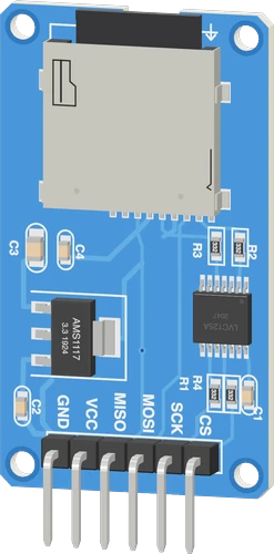
The Catalex (HW-125) microSD module is a microSD socket on SPI with an AMS1117-3.3 regulator, which needs at least 1.1 V of headroom (AMS1117 datasheet, p. 3), and a 74LVC125A buffer whose inputs accept 5.5 V (TI SN74LVC125A datasheet, p. 1). Power VCC from 5 V, never 3.3 V, wire SCK, MOSI and MISO to the board's hardware SPI pins and CS to any digital pin, then call SD.begin(csPin).
The Catalex MicroSD Card Adapter, sold under many names including HW-125, is the usual way to log data to a microSD card from an Arduino, ESP32 or Raspberry Pi Pico. It carries a push-push microSD socket, an AMS1117-3.3 linear regulator that turns the 5 V on VCC into the card's 3.3 V, and a 74LVC125A quad buffer that translates the SPI lines. Its 6-pin header is GND, VCC, MISO, MOSI, SCK and CS.
The 74LVC125A runs from 1.65 V to 3.6 V but its inputs accept up to 5.5 V, so it lets 5 V and 3.3 V devices share a bus (TI SN74LVC125A datasheet, p. 1). On this module it sits on the 3.3 V rail: a 5 V Arduino's SCK, MOSI and CS are brought down to 3.3 V for the card, and the card's data out reaches MISO as a 3.3 V signal. The card itself is an SD-standard part powered at 2.7 V to 3.6 V and talking in SPI mode.
Two board-level details matter. The AMS1117's dropout is 1.1 V typical and 1.3 V maximum at 0.8 A (AMS1117 datasheet, p. 3), so VCC must be 5 V: on 3.3 V the card sees too little and SD.begin() fails. And on the common Catalex layout the buffer driving MISO has its enable tied to ground, so the module keeps driving MISO even when CS is high (CircuitState's traced schematic). Another SPI device on the same MISO line, such as an RC522 reader or a touch controller, then reads garbage; give the card its own SPI bus or use a module that releases MISO.
MicroSD Card Module pinout
| Pin | Function | Type |
|---|---|---|
| GND | GND | power in |
| VCC | VCC (5 V, into the AMS1117-3.3)4.5–5 V | power in |
| MISO | SPI MISO | output |
| MOSI | SPI MOSI | input |
| SCK | SPI SCK | input |
| CS | SPI CS | input |
How to wire the MicroSD Card Module
Pin by pin, for the board you have.
| MicroSD Card Module | Arduino Uno | Note |
|---|---|---|
| VCC | 5V | |
| GND | GND | |
| SCK | D13 | |
| MOSI | D11 | |
| MISO | D12 | |
| CS | D10 |
| MicroSD Card Module | ESP32 DevKit V1 | Note |
|---|---|---|
| VCC | VIN | |
| GND | GND | |
| SCK | GPIO18 (D18) | |
| MOSI | GPIO23 (D23) | |
| MISO | GPIO19 (D19) | |
| CS | GPIO13 (D13) |
- VCC is on VIN, which gives about 5 V only while the board is powered from USB.
| MicroSD Card Module | Raspberry Pi Pico | Note |
|---|---|---|
| VCC | VBUS | |
| GND | GND | |
| SCK | GP18 | |
| MOSI | GP19 | |
| MISO | GP16 | |
| CS | GP0 |
- VCC is on VBUS, which gives about 5 V only while the board is powered from USB.
MicroSD Card Module code
Every example here compiles for its board.
// MicroSD Card Module on Arduino Uno: wiring and a free simulation at https://www.tinkered.ai/components/microsd-module
#include <SPI.h>
#include <SD.h>

const int SD_CS = 10;

void setup() {
  Serial.begin(115200);
  if (!SD.begin(SD_CS)) {
    Serial.println("No card, or the wiring is wrong");
    while (1) delay(10);
  }
  File f = SD.open("/LOG.TXT", FILE_WRITE);
  if (f) {
    f.println(millis());
    f.close();
  }
  f = SD.open("/LOG.TXT");
  while (f && f.available()) Serial.write(f.read());
  if (f) f.close();
}

void loop() {}
// MicroSD Card Module on ESP32 DevKit V1: wiring and a free simulation at https://www.tinkered.ai/components/microsd-module
#include <SPI.h>
#include <SD.h>

const int SD_CS = 13;

void setup() {
  Serial.begin(115200);
  if (!SD.begin(SD_CS)) {
    Serial.println("No card, or the wiring is wrong");
    while (1) delay(10);
  }
  File f = SD.open("/LOG.TXT", FILE_APPEND);
  if (f) {
    f.println(millis());
    f.close();
  }
  f = SD.open("/LOG.TXT");
  while (f && f.available()) Serial.write(f.read());
  if (f) f.close();
}

void loop() {}
// MicroSD Card Module on Raspberry Pi Pico: wiring and a free simulation at https://www.tinkered.ai/components/microsd-module
#include <SPI.h>
#include <SD.h>

const int SD_CS = 0;

void setup() {
  Serial.begin(115200);
  if (!SD.begin(SD_CS)) {
    Serial.println("No card, or the wiring is wrong");
    while (1) delay(10);
  }
  File f = SD.open("/LOG.TXT", FILE_WRITE);
  if (f) {
    f.println(millis());
    f.close();
  }
  f = SD.open("/LOG.TXT");
  while (f && f.available()) Serial.write(f.read());
  if (f) f.close();
}

void loop() {}
// MicroSD Card Module on STM32 Blue Pill (F103C8): wiring and a free simulation at https://www.tinkered.ai/components/microsd-module
#include <SPI.h>
#include <SD.h>

const int SD_CS_PIN = 10;   // the CS pin wired (IO5 on an ESP32 DevKit, 17 on a Pico, D8 on a NodeMCU, PA4 on an STM32)

void setup() {
  Serial.begin(115200);
  if (!SD.begin(SD_CS_PIN)) {
    Serial.println("SD card not found: check the card, VCC on 5 V and the wiring");
    while (true) delay(1000);
  }
  // a file the folder gave the card (sdcard/card1/CONFIG.TXT)
  File config = SD.open("/CONFIG.TXT");   // paths from "/": the ESP32 refuses one without it
  if (config) {
    while (config.available()) Serial.write(config.read());
    config.close();
  }
}

void loop() {
#if defined(ESP32)
  File log = SD.open("/LOG.CSV", FILE_APPEND);  // the ESP32's FILE_WRITE would empty the file first
#else
  File log = SD.open("/LOG.CSV", FILE_WRITE);   // appends
#endif
  if (log) {
    log.print(millis());
    log.print(',');
    log.println(analogRead(A0));
    log.close();                                // on the card now
  }
  delay(1000);
}
Before you wire it
- VCC to the board's 5 V pin (5V on the Uno, Mega, Nano, UNO R4 and STM32 boards; VIN on the ESP32 DevKit and the NodeMCU; VBUS on the Pico). GND to GND.
- SCK, MOSI, MISO on the board's hardware SPI pins (table below); CS on a free GPIO, passed to SD.begin(cs).
- One SPI part per MISO line with this module (rule above). A second module needs its own card: card=card2 on its line.
- File names: Arduino's SD library (SD.h on the Uno, Mega, Nano, UNO R4 and STM32 boards) takes 8.3 names only (LOG.TXT, DATA01.CSV). The ESP32, ESP8266 and Pico cores' SD libraries, and SdFat.h, take long names. Start every path with / (SD.open("/LOG.TXT")): every core takes it, and the ESP32's refuses a path without it ("LOG.TXT" opens nothing). On the ESP32 FILE_WRITE empties the file first: append with FILE_APPEND (on the other cores FILE_WRITE appends).
- Close (or flush()) a file before the sketch moves on: what is not flushed is not on the card, on the board and here.
- No VCC on 3.3 V: the regulator leaves the card too little.
- No sharing this module's MISO with an RC522 or another SPI reader.
- No long file names with Arduino's SD library (Uno, Mega, Nano, R4, STM32): use 8.3 names or SdFat.
- Power VCC from the board's 5 V pin: 5V on an Uno, Nano or Mega, VIN on an ESP32 DevKit, VBUS on a Pico. The AMS1117 needs at least 1.1 V to 1.3 V of headroom above its 3.3 V output (AMS1117 datasheet, p. 3).
- Connect SCK, MOSI and MISO to the board's hardware SPI pins (D13, D11, D12 on an Uno; GPIO18, 23, 19 on an ESP32; GP18, GP19, GP16 on a Pico) and CS to any free GPIO passed to SD.begin(cs).
- The module works on 3.3 V boards without extra parts: the 74LVC125A runs from the module's 3.3 V rail, so MISO reaches the board at 3.3 V, and its inputs accept the board's 3.3 V or 5 V signals (TI SN74LVC125A datasheet, p. 1).
- Keep this module alone on its MISO line. Its MISO buffer stays enabled when CS is high, so a second SPI device on the same MISO cannot answer.
- On an Uno keep D10, and on a Mega D53, set as an OUTPUT even if CS is on another pin: it is the AVR's hardware SS pin, and as a low input it drops SPI into slave mode.
- Format the card FAT16 or FAT32 (cards up to 32 GB), use 8.3 file names with Arduino's SD library, and close() or flush() files so the data is written to the card.
- Its 74LVC125A buffer runs on the module's 3.3 V regulator, so MISO is already a 3.3 V signal: no divider on MISO for an ESP32 or a Pico.
Specifications
- Module supply
- 5 V on VCC (AMS1117-3.3 regulator)Module schematic; AMS1117 datasheet, p. 3
- Regulator dropout
- 1.1 V typical, 1.3 V maximum at 0.8 AAdvanced Monolithic Systems AMS1117 datasheet, p. 3
- Regulator output
- 3.3 V, up to 1 AAdvanced Monolithic Systems AMS1117 datasheet, p. 1
- Level shifter
- 74LVC125A: 1.65 V to 3.6 V supply, inputs accept 5.5 VTI SN74LVC125A datasheet SCAS290T, p. 1
- Buffer propagation delay
- 4.8 ns maximum at 3.3 VTI SN74LVC125A datasheet SCAS290T, p. 1
- Card supply
- 2.7 V to 3.6 VSD Association Physical Layer Simplified Specification
- Interface
- SPI: SCK, MOSI, MISO, CS (active low)Module pinout
- MISO behaviour
- Driven at all times on the common Catalex layout (buffer enable tied low)CircuitState Catalex module schematic
- Supply voltage
- 4.5–5 V
- Maximum supply voltage
- 5.5 V
- Dimensions
- 24 × 7.3 × 46.2 mm
- Weight
- 3 g
From the Catalex (generic HW-125)'s datasheet, published by Catalex (generic HW-125).
Common mistakes
Powering VCC from 3.3 V
The AMS1117 drops 1.1 V typical (datasheet, p. 3), so a 3.3 V supply leaves the card well below its 2.7 V minimum and SD.begin() fails. Feed VCC 5 V even on an ESP32 or Pico.
Sharing MISO with another SPI device
On the common Catalex board the MISO buffer is always enabled, so it keeps driving the line while another device's CS is low. An RC522 or a TFT's touch controller then reads 0xFF or garbage. Use a separate SPI bus for the card.
Long file names with SD.h
Arduino's SD library on AVR boards takes 8.3 names only, so DATALOG_2024.CSV fails to open. Use names like LOG.TXT or DATA01.CSV, or the SdFat library.
Not closing the file
Data written to a File sits in a buffer until flush() or close(). Pulling power or resetting before that leaves an empty or truncated file.
Unsupported card format
exFAT cards (most 64 GB and larger) are not read by Arduino's SD library. Format the card FAT32, or use a 32 GB or smaller card.
MicroSD Card Module questions
How do I connect a microSD card module to an Arduino Uno?
VCC to 5V, GND to GND, SCK to D13, MOSI to D11, MISO to D12 and CS to D10, then #include <SD.h> and call SD.begin(10). VCC must be 5 V because the module's AMS1117-3.3 regulator needs about 1.1 V of headroom (AMS1117 datasheet, p. 3).
Can I use the microSD module with an ESP32 or Raspberry Pi Pico?
Yes. Power VCC from VIN (ESP32) or VBUS (Pico), not 3V3, and wire the SPI pins directly. The 74LVC125A runs on the module's 3.3 V rail and accepts inputs up to 5.5 V (TI SN74LVC125A datasheet, p. 1), so it is safe at 3.3 V logic. On the ESP32 start every path with /, as in SD.open("/LOG.TXT").
Why does SD.begin() fail?
The usual causes are VCC on 3.3 V instead of 5 V, MISO shared with another SPI device, the wrong CS pin in SD.begin(), a card formatted exFAT, or loose jumper wires on the SPI lines. Check the 5 V supply first: the AMS1117 needs 1.1 V to 1.3 V above its 3.3 V output (datasheet, p. 3).
Can the microSD module share the SPI bus with an RFID reader or display?
Not reliably on the common Catalex board: its MISO buffer has its enable tied low, so it drives MISO even when its CS is high (CircuitState's traced schematic). Give the card module its own SPI pins, or choose a breakout that tri-states MISO.
What size and format of microSD card should I use?
A microSD or microSDHC card up to 32 GB formatted FAT32 (or FAT16 for small cards). Arduino's SD library does not read exFAT, the default format of most 64 GB and larger cards.
Does the microSD module work at 3.3 V logic?
Yes. The logic is translated by the 74LVC125A, whose inputs accept 3.3 V or 5 V signals (TI SN74LVC125A datasheet, p. 1). Only the module's supply must be 5 V.
Build something with the MicroSD Card Module
- Build this
Temperature and humidity logger
Append a timestamped CSV line from a DHT22 or BME280 every minute for weeks of data.
- Build this
GPS track recorder
Write NEO-6M positions to a GPX or CSV file for a bike ride or a hike.
- Build this
WAV audio player
Stream sound files from the card to an I2S amplifier or a DAC.
- Build this
Configuration file reader
Keep Wi-Fi credentials and settings in a text file on the card instead of in the sketch.
This page as plain Markdown, for ChatGPT, Claude or your own agent. /components/microsd-module.md