ST7789 TFT 1.54"
Adafruit's 1.54-inch 240 × 240 wide-angle IPS display with an ST7789, a microSD slot, a regulator and 3 V to 5 V logic on every input.
- Panel1.54-inch IPS, 240 × 240 pixels, wide viewing angle
- ControllerSitronix ST7789, 240 × 320 frame memory, up to 262K colours
- Power (Vin)3 V to 5 V, on-board regulator with reverse polarity protection; 3V pin is the regulator's 3.3 V output
- Logic levelsCL, SI, TC, RT, DC, CC and BL accept 3 V to 5 V logic; SO is 3.3 V out
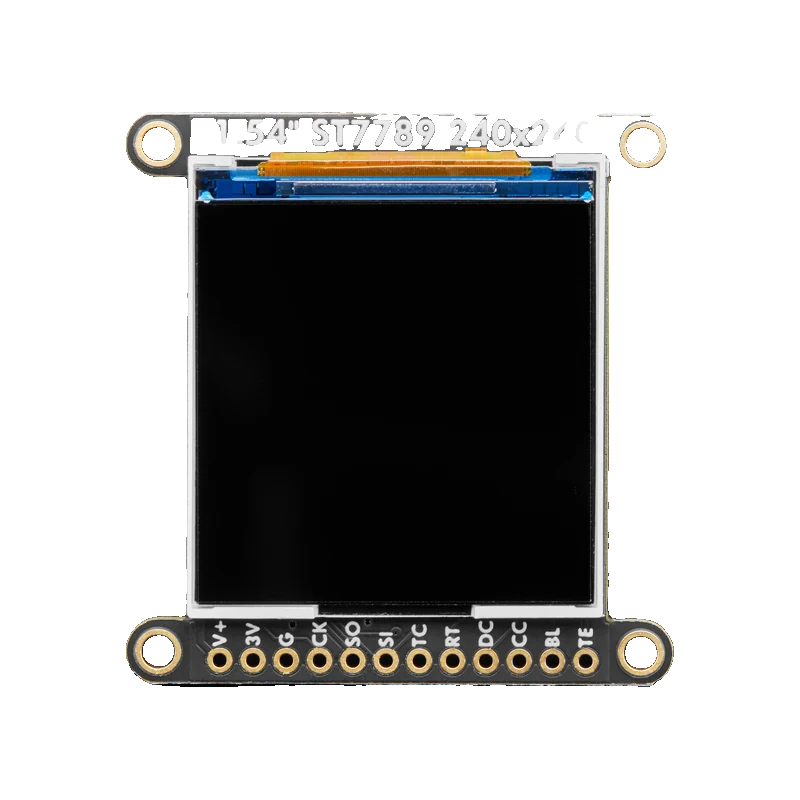
Adafruit's 1.54-inch ST7789 board is a 240 × 240 IPS colour display with a microSD slot: Vin takes 3 V to 5 V through an on-board regulator, and SCK, MOSI, CS, DC, RST and the card CS all accept 3 V to 5 V logic (Adafruit 240 × 240 TFT guide, Pinouts). It wires straight to an Uno, an ESP32 or a Pico over SPI with its own CS pin, and Adafruit_ST7789 starts it with init(240, 240). The ST7789 itself is a 3.3 V controller with a 240 × 320 frame memory and up to 262K colours (Sitronix ST7789V Datasheet V1.3, pp. 13 to 14).
This board takes the same Sitronix ST7789 used on bare 240 × 240 modules and adds what the bare modules lack: a 3.3 V regulator with reverse polarity protection, level shifting on every input, a CS pin of its own, an automatic reset circuit and a microSD socket on the back (Adafruit 240 × 240 TFT guide, Pinouts). The result is a display that can share its SPI bus with the card or other devices and that a 5 V Uno drives with no extra parts.
The 1.54-inch IPS panel is larger than the common 1.3-inch modules at the same 240 × 240 resolution, with wide viewing angles. The ST7789 keeps its own frame memory (Sitronix ST7789V Datasheet V1.3, p. 13), so a sketch redraws only what changes, and its backlight input (BL) is pulled high so the screen lights up with nothing connected, or dims with PWM.
Pins are printed with short names: Vin, 3V, G, CL (clock), SO (MISO, for the card), SI (MOSI), TC (display CS), RT (reset), DC, CC (card CS) and BL. Recent versions also carry an 18-pin EYESPI flex connector, so the display can be cabled to a controller without soldering headers.
ST7789 TFT 1.54" pinout
| Pin | Function | Type |
|---|---|---|
| Vin | Supply3 V to 5 V | power in |
| 3V | 3.3 V regulator output | power out |
| G | Ground | power in |
| CL | SPI SCK3 V to 5 V | input |
| SO | SPI MISO (SD card only)3.3 V | output |
| SI | SPI MOSI3 V to 5 V | input |
| TC | TFT CS (active low)3 V to 5 V | input |
| RT | TFT reset (active low)3 V to 5 V | input |
| DC | Data / command select3 V to 5 V | input |
| CC | SD card CS (active low)3 V to 5 V | input |
| BL | Backlight, PWM3 V to 5 V | input |
How to wire the ST7789 TFT 1.54"
Pin by pin, for the board you have.
| ST7789 TFT 1.54" | Arduino Uno | Note |
|---|---|---|
| Vin | 5V | |
| G | GND | |
| CL | D13 | |
| SI | D11 | |
| TC | D10 | |
| DC | D9 | |
| RT | D8 |
| ST7789 TFT 1.54" | ESP32 DevKit V1 | Note |
|---|---|---|
| Vin | 3V3 | |
| G | GND | |
| CL | GPIO18 (D18) | |
| SI | GPIO23 (D23) | |
| TC | GPIO5 (D5) | |
| DC | GPIO16 (RX2) | |
| RT | GPIO17 (TX2) |
| ST7789 TFT 1.54" | Raspberry Pi Pico | Note |
|---|---|---|
| Vin | 3V3(OUT) | |
| G | GND | |
| CL | GP18 | |
| SI | GP19 | |
| TC | GP17 | |
| DC | GP21 | |
| RT | GP20 |
ST7789 TFT 1.54" code
Every example here compiles for its board.
// ST7789 TFT 1.54" on Arduino Uno: wiring and a free simulation at https://www.tinkered.ai/components/st7789-tft-1-54
// Adafruit 1.54" ST7789 240x240 on an Arduino Uno: CL D13, SI D11, TC D10, DC D9, RT D8
#include <SPI.h>
#include <Adafruit_GFX.h>
#include <Adafruit_ST7789.h>

const int TFT_CS = 10;
const int TFT_DC = 9;
const int TFT_RST = 8;
Adafruit_ST7789 tft(TFT_CS, TFT_DC, TFT_RST);

void setup() {
  Serial.begin(115200);
  tft.init(240, 240); // SPI mode 0 works on this board, it has a CS pin
  tft.fillScreen(ST77XX_BLACK);
  tft.fillRoundRect(10, 10, 220, 60, 8, ST77XX_BLUE);
  tft.setTextColor(ST77XX_WHITE);
  tft.setTextSize(3);
  tft.setCursor(30, 28);
  tft.print(F("1.54 TFT"));
  tft.setTextColor(ST77XX_YELLOW, ST77XX_BLACK);
  Serial.println(F("Display ready"));
}

void loop() {
  static unsigned long seconds = 0;
  tft.setTextSize(5);
  tft.setCursor(30, 120);
  tft.print(seconds);
  tft.print(F("  "));
  Serial.print(F("Uptime: "));
  Serial.println(seconds);
  seconds++;
  delay(1000);
}
// ST7789 TFT 1.54" on ESP32 DevKit V1: wiring and a free simulation at https://www.tinkered.ai/components/st7789-tft-1-54
// Adafruit 1.54" ST7789 240x240 on an ESP32 DevKit V1: CL GPIO18, SI GPIO23, TC GPIO5, DC GPIO16, RT GPIO17
#include <SPI.h>
#include <Adafruit_GFX.h>
#include <Adafruit_ST7789.h>

const int TFT_CS = 5;
const int TFT_DC = 16;
const int TFT_RST = 17;
Adafruit_ST7789 tft(TFT_CS, TFT_DC, TFT_RST);

void setup() {
  Serial.begin(115200);
  tft.init(240, 240);
  tft.fillScreen(ST77XX_BLACK);
  tft.fillRoundRect(10, 10, 220, 60, 8, ST77XX_BLUE);
  tft.setTextColor(ST77XX_WHITE);
  tft.setTextSize(3);
  tft.setCursor(30, 28);
  tft.print("1.54 TFT");
  tft.setTextColor(ST77XX_YELLOW, ST77XX_BLACK);
  Serial.println("Display ready");
}

void loop() {
  static unsigned long seconds = 0;
  tft.setTextSize(5);
  tft.setCursor(30, 120);
  tft.printf("%lu  ", seconds);
  Serial.printf("Uptime: %lu s\n", seconds);
  seconds++;
  delay(1000);
}
// ST7789 TFT 1.54" on Raspberry Pi Pico: wiring and a free simulation at https://www.tinkered.ai/components/st7789-tft-1-54
// Adafruit 1.54" ST7789 240x240 on a Raspberry Pi Pico (arduino-pico): CL GP18, SI GP19, TC GP17, DC GP21, RT GP20
#include <SPI.h>
#include <Adafruit_GFX.h>
#include <Adafruit_ST7789.h>

const int TFT_CS = 17;
const int TFT_DC = 21;
const int TFT_RST = 20;
Adafruit_ST7789 tft(TFT_CS, TFT_DC, TFT_RST);

void setup() {
  Serial.begin(115200);
  SPI.setSCK(18);
  SPI.setTX(19);
  tft.init(240, 240);
  tft.fillScreen(ST77XX_BLACK);
  tft.fillRoundRect(10, 10, 220, 60, 8, ST77XX_BLUE);
  tft.setTextColor(ST77XX_WHITE);
  tft.setTextSize(3);
  tft.setCursor(30, 28);
  tft.print("1.54 TFT");
  tft.setTextColor(ST77XX_YELLOW, ST77XX_BLACK);
  Serial.println("Display ready");
}

void loop() {
  static unsigned long seconds = 0;
  tft.setTextSize(5);
  tft.setCursor(30, 120);
  tft.print(seconds);
  tft.print("  ");
  Serial.print("Uptime: ");
  Serial.println(seconds);
  seconds++;
  delay(1000);
}
Before you wire it
- Initialise with tft.init(240, 240); this board has a CS pin, so the default SPI mode 0 works.
- Power Vin from 3 V to 5 V (Adafruit 240 × 240 TFT guide, Pinouts); use the board's 5V on an Uno and 3V3 on an ESP32 or Pico.
- Give the display (TC) and the microSD card (CC) separate CS pins when both are used.
- Wire the clock to the board's hardware SPI SCK and SI to MOSI.
- Never feed the 3V pin from outside: it is the regulator's output.
- Never let CC float while a card is inserted and the bus is in use: drive it high from a spare GPIO.
- Never pick ESP32 strapping pins (0, 2, 12, 15) for DC or RT when free pins exist.
- SO is only needed to read the microSD card; the display itself is write-only (Adafruit 240 × 240 TFT guide, Pinouts).
- RT can be tied to the microcontroller's reset, but the guide recommends letting the library drive it for a clean reset.
- BL is pulled high, so the backlight is on with nothing connected; a PWM pin on BL dims it.
- The same Adafruit_ST7789 code drives the 1.3-inch version of this board; only the pin names differ slightly (Adafruit guide, Pinouts).
- On the ESP32 and RP2040, Adafruit's library runs the SPI clock much faster than on an Uno, so full-screen redraws take a fraction of the time.
Specifications
- Panel
- 1.54-inch IPS, 240 × 240 pixels, wide viewing angleAdafruit product 3787 page
- Controller
- Sitronix ST7789, 240 × 320 frame memory, up to 262K coloursSitronix ST7789V Datasheet V1.3, p. 13
- Power (Vin)
- 3 V to 5 V, on-board regulator with reverse polarity protection; 3V pin is the regulator's 3.3 V outputAdafruit 240 × 240 TFT guide, Pinouts
- Logic levels
- CL, SI, TC, RT, DC, CC and BL accept 3 V to 5 V logic; SO is 3.3 V outAdafruit 240 × 240 TFT guide, Pinouts
- Controller logic supply
- VDDI 1.65 V to 3.3 V (handled by the board)Sitronix ST7789V Datasheet V1.3, p. 14
- Backlight
- BL pulled high (on) by default; PWM at any frequency to dimAdafruit 240 × 240 TFT guide, Pinouts
- Extras
- microSD card socket on SPI (CC chip select), 18-pin 0.5 mm EYESPI connectorAdafruit 240 × 240 TFT guide, Pinouts and EYESPI
From the Adafruit 1.3" and 1.54" 240 x 240 Wide Angle TFT LCD Displays guide, published by Sitronix (ST7789), board by Adafruit.
Common mistakes
Using SPI_MODE2 from no-CS examples
Code written for bare 7-pin ST7789 modules calls init(240, 240, SPI_MODE2). This board has a CS pin and works with the default mode; use init(240, 240) and pass the TC pin to the constructor.
Confusing the 1.3-inch and 1.54-inch labels
Adafruit's 1.3-inch board prints longer names (SCK, TCS, RST, D/C, CCS, Lite) where the 1.54-inch prints CL, TC, RT, DC, CC and BL (Adafruit guide, Pinouts). The functions are the same; match by function, not by label.
Card and display fighting over SPI
With a card inserted and CC floating, the card can answer while the display is being written. Drive CC from a GPIO and keep it high whenever the card is not in use.
ST7789 TFT 1.54" questions
Can I use the Adafruit 1.54-inch ST7789 with a 5 V Arduino?
Yes. Vin accepts 3 V to 5 V and the inputs are level shifted for 3 V to 5 V logic (Adafruit 240 × 240 TFT guide, Pinouts), so wire it straight to the Uno's 5V and SPI pins.
What resolution is the 1.54-inch ST7789?
240 × 240 pixels on a 1.54-inch IPS panel. The ST7789's own memory is 240 × 320 (Sitronix ST7789V Datasheet V1.3, p. 13); the library maps the 240 × 240 window for you.
How is it different from the cheap 1.3-inch 7-pin modules?
It adds a regulator, input level shifting, a CS pin, an automatic reset, a microSD slot and an EYESPI connector. The bare modules are 3.3 V only and lack CS, so they need SPI mode 2 and cannot share the bus.
Which library should I use?
Adafruit's ST7735 and ST7789 library with Adafruit GFX, which Adafruit's guide uses. TFT_eSPI and LovyanGFX also drive the ST7789 and are faster on ESP32 and RP2040 boards.
Can I load images from the microSD card?
Yes: wire SO to MISO and CC to a spare pin, and use Adafruit_ImageReader with the SD library to draw BMP files from the card.
Build something with the ST7789 TFT 1.54"
- Build this
Photo frame
Cycle through BMP images from the microSD card.
- Build this
Air quality badge
CO2 and temperature with a colour-coded background.
This page as plain Markdown, for ChatGPT, Claude or your own agent. /components/st7789-tft-1-54.md