ST7789 TFT 1.3"
A 1.3-inch 240 × 240 IPS colour display on a 7-pin SPI board with no chip-select pin, driven by Sitronix's ST7789.
- ControllerSitronix ST7789, 240 × 320 frame memory, up to 262K colours
- Logic supply (VDDI)1.65 V to 3.3 V
- Analog supply (VDD)2.4 V to 3.3 V
- Absolute maximumVDD and VDDI 4.6 V; logic inputs -0.3 V to VDDI + 0.5 V
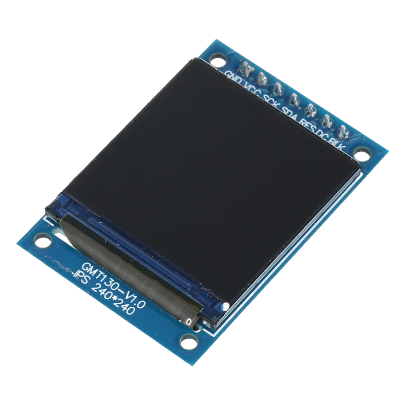
The 1.3-inch ST7789 module is a 240 × 240 pixel IPS colour screen on a 7-pin header (GND, VCC, SCL, SDA, RES, DC, BLK) with no CS pin, driven by Sitronix's ST7789, whose logic runs at 1.65 V to 3.3 V and accepts at most VDDI + 0.5 V on its inputs (Sitronix ST7789V Datasheet V1.3, pp. 14, 37). Power it from 3.3 V, wire SCL and SDA to the board's hardware SPI clock and MOSI, and start Adafruit_ST7789 with init(240, 240, SPI_MODE2), the SPI mode a board without CS needs. A 5 V Uno needs a level shifter on its four signal lines.
This small square IPS panel shows 240 × 240 pixels in 16-bit colour with wide viewing angles, a popular step up from 0.96-inch OLEDs for watch faces, gauges and menus. The ST7789 controller holds a 240 × 320 frame memory of its own and supports up to 262K colours (Sitronix ST7789V Datasheet V1.3, p. 13), so the microcontroller only sends pixels when something changes.
The board prints SCL and SDA on its pins, but the bus is SPI, not I2C: SCL is the SPI clock and SDA is MOSI, data into the display. RES resets the controller, DC selects command or data, and BLK switches the backlight. Because there is no CS pin, the controller is always selected, which is why it must run in SPI mode 2 or 3 (clock idling high) and cannot share the SPI bus with another device.
The ST7789 is a 3.3 V part: its inputs read high from 0.7 × VDDI and must stay below VDDI + 0.5 V (pp. 37 to 38). On an ESP32 or a Pico everything wires directly. On a 5 V Uno, a 74HC4050 buffer powered from 3.3 V brings SCL, SDA, RES and DC down to 3.3 V, and a 240 × 240 screen redraw takes noticeably longer than on the 32-bit boards.
ST7789 TFT 1.3" pinout
| Pin | Function | Type |
|---|---|---|
| GND | Ground | power in |
| VCC | Supply3.3 V | power in |
| SCL | SPI SCK3.3 V only | input |
| SDA | SPI MOSI3.3 V only | input |
| RES | Reset (active low)3.3 V only | input |
| DC | Data / command select3.3 V only | input |
| BLK | Backlight control, PWM | input |
How to wire the ST7789 TFT 1.3"
Pin by pin, for the board you have.
| ST7789 TFT 1.3" | Arduino Uno | Note |
|---|---|---|
| GND | GND | |
| VCC | 3.3 V regulator output (AMS1117-3.3 module fed from 5V) | Keeps the backlight current off the Uno's 50 mA 3.3V pin. |
| SCL | D13 through a 74HC4050 buffer powered from 3.3 V | |
| SDA | D11 through the 74HC4050 | |
| RES | D8 through the 74HC4050 | |
| DC | D9 through the 74HC4050 | |
| BLK | Not connected (backlight on) |
- The ST7789's inputs accept at most VDDI + 0.5 V (Sitronix datasheet V1.3, p. 37): 5 V straight from the Uno exceeds it, so buffer all four signal lines.
| ST7789 TFT 1.3" | ESP32 DevKit V1 | Note |
|---|---|---|
| GND | GND | |
| VCC | 3V3 | |
| SCL | GPIO18 (D18) | |
| SDA | GPIO23 (D23) | |
| RES | GPIO17 (TX2) | |
| DC | GPIO16 (RX2) | |
| BLK | Not connected (backlight on) |
| ST7789 TFT 1.3" | Raspberry Pi Pico | Note |
|---|---|---|
| GND | GND | |
| VCC | 3V3(OUT) | |
| SCL | GP18 | |
| SDA | GP19 | |
| RES | GP20 | |
| DC | GP21 | |
| BLK | Not connected (backlight on) |
ST7789 TFT 1.3" code
Every example here compiles for its board.
// ST7789 TFT 1.3" on Arduino Uno: wiring and a free simulation at https://www.tinkered.ai/components/st7789-tft-1-3
// 1.3" ST7789 240x240 (no CS pin) on an Arduino Uno through a 74HC4050: SCL D13, SDA D11, RES D8, DC D9
#include <SPI.h>
#include <Adafruit_GFX.h>
#include <Adafruit_ST7789.h>

const int TFT_CS = -1; // the module has no CS pin
const int TFT_DC = 9;
const int TFT_RST = 8;
Adafruit_ST7789 tft(TFT_CS, TFT_DC, TFT_RST);

void setup() {
  Serial.begin(115200);
  tft.init(240, 240, SPI_MODE2); // boards without CS need SPI mode 2 (or 3)
  tft.setRotation(0);
  tft.fillScreen(ST77XX_BLACK);
  tft.setTextColor(ST77XX_WHITE, ST77XX_BLACK);
  tft.setTextSize(3);
  tft.setCursor(20, 30);
  tft.print(F("ST7789"));
  tft.drawRect(10, 20, 220, 50, ST77XX_CYAN);
  Serial.println(F("Display ready"));
}

void loop() {
  static unsigned long seconds = 0;
  tft.setTextSize(4);
  tft.setCursor(20, 120);
  tft.print(seconds);
  tft.print(F(" s  "));
  Serial.print(F("Uptime: "));
  Serial.println(seconds);
  seconds++;
  delay(1000);
}
// ST7789 TFT 1.3" on ESP32 DevKit V1: wiring and a free simulation at https://www.tinkered.ai/components/st7789-tft-1-3
// 1.3" ST7789 240x240 (no CS pin) on an ESP32 DevKit V1: SCL GPIO18, SDA GPIO23, RES GPIO17, DC GPIO16
#include <SPI.h>
#include <Adafruit_GFX.h>
#include <Adafruit_ST7789.h>

const int TFT_CS = -1;
const int TFT_DC = 16;
const int TFT_RST = 17;
Adafruit_ST7789 tft(TFT_CS, TFT_DC, TFT_RST);

void setup() {
  Serial.begin(115200);
  tft.init(240, 240, SPI_MODE2);
  tft.setRotation(0);
  tft.fillScreen(ST77XX_BLACK);
  tft.setTextColor(ST77XX_WHITE, ST77XX_BLACK);
  tft.setTextSize(3);
  tft.setCursor(20, 30);
  tft.print("ST7789");
  tft.drawRect(10, 20, 220, 50, ST77XX_CYAN);
  Serial.println("Display ready");
}

void loop() {
  static unsigned long seconds = 0;
  tft.setTextSize(4);
  tft.setCursor(20, 120);
  tft.printf("%lu s  ", seconds);
  Serial.printf("Uptime: %lu s\n", seconds);
  seconds++;
  delay(1000);
}
// ST7789 TFT 1.3" on Raspberry Pi Pico: wiring and a free simulation at https://www.tinkered.ai/components/st7789-tft-1-3
// 1.3" ST7789 240x240 (no CS pin) on a Raspberry Pi Pico (arduino-pico): SCL GP18, SDA GP19, RES GP20, DC GP21
#include <SPI.h>
#include <Adafruit_GFX.h>
#include <Adafruit_ST7789.h>

const int TFT_CS = -1;
const int TFT_DC = 21;
const int TFT_RST = 20;
Adafruit_ST7789 tft(TFT_CS, TFT_DC, TFT_RST);

void setup() {
  Serial.begin(115200);
  SPI.setSCK(18);
  SPI.setTX(19);
  tft.init(240, 240, SPI_MODE2);
  tft.setRotation(0);
  tft.fillScreen(ST77XX_BLACK);
  tft.setTextColor(ST77XX_WHITE, ST77XX_BLACK);
  tft.setTextSize(3);
  tft.setCursor(20, 30);
  tft.print("ST7789");
  tft.drawRect(10, 20, 220, 50, ST77XX_CYAN);
  Serial.println("Display ready");
}

void loop() {
  static unsigned long seconds = 0;
  tft.setTextSize(4);
  tft.setCursor(20, 120);
  tft.print(seconds);
  tft.print(" s  ");
  Serial.print("Uptime: ");
  Serial.println(seconds);
  seconds++;
  delay(1000);
}
Before you wire it
- Initialise with tft.init(240, 240, SPI_MODE2) (or SPI_MODE3): with no CS pin the ST7789 only syncs to a clock that idles high.
- Keep every signal at 3.3 V: inputs accept at most VDDI + 0.5 V (Sitronix ST7789V Datasheet V1.3, p. 37).
- Wire SCL to the hardware SPI clock and SDA to MOSI, never to the I2C pins.
- Pass -1 as the CS pin in the constructor.
- Never connect the display to an Uno's pins without a 3.3 V buffer or level shifter.
- Never share its SPI bus with an SD card or radio: without CS it listens to all traffic.
- Never use ESP32 strapping pins (0, 2, 5, 12, 15) for RES or DC if you can avoid it; GPIO16 and GPIO17 are free choices.
- SCL and SDA on this board are SPI signals; the names are a labelling habit of these modules, not an I2C interface.
- BLK is held high on these boards so the backlight comes on with BLK left open; if yours stays dark, tie BLK to 3.3 V, or drive it from a PWM pin to dim the screen.
- Colours and text look inverted or the image is shifted on some batches; tft.invertDisplay(true) and setRotation() fix most cases.
- The 74HC4050 is a good down-shifter here: powered from 3.3 V its inputs tolerate 5 V and it is fast enough for SPI at several MHz.
- The ST7789's frame memory is 240 × 320; the library offsets the 240 × 240 window, so use init(240, 240) rather than a 320-line size.
Specifications
- Controller
- Sitronix ST7789, 240 × 320 frame memory, up to 262K coloursSitronix ST7789V Datasheet V1.3, p. 13
- Logic supply (VDDI)
- 1.65 V to 3.3 VSitronix ST7789V Datasheet V1.3, p. 14
- Analog supply (VDD)
- 2.4 V to 3.3 VSitronix ST7789V Datasheet V1.3, p. 14
- Absolute maximum
- VDD and VDDI 4.6 V; logic inputs -0.3 V to VDDI + 0.5 VSitronix ST7789V Datasheet V1.3, p. 37
- Input threshold
- High from 0.7 × VDDI, low up to 0.3 × VDDISitronix ST7789V Datasheet V1.3, p. 38
- SPI write clock
- 66 ns minimum serial clock cycle (about 15 MHz in specification)Sitronix ST7789V Datasheet V1.3, p. 43
- Panel
- 1.3-inch IPS, 240 × 240 pixels, 7-pin header without CSModule silkscreen and listing (GMT130-V1.0 board)
From the Sitronix ST7789V Datasheet Version 1.3, published by Sitronix.
Common mistakes
Black screen with SPI_MODE0
Most ST7789 examples are written for boards with a CS pin and use SPI mode 0. Without CS the controller never sees the start of a transfer in that mode. Call tft.init(240, 240, SPI_MODE2) and the display comes up.
Wiring SCL and SDA to the I2C pins
The silkscreen says SCL and SDA, but the bus is SPI. Connect SCL to the board's SPI clock (D13, GPIO18, GP18) and SDA to MOSI (D11, GPIO23, GP19).
5 V signals from an Uno
The controller's inputs are limited to VDDI + 0.5 V (Sitronix ST7789V Datasheet V1.3, p. 37). Plenty of tutorials wire it straight to an Uno and it may work for a while; a 74HC4050 buffer on 3.3 V keeps it within ratings.
Wrong size in init()
Initialising as 240 × 320 or 135 × 240 shifts or wraps the image. This panel is 240 × 240.
ST7789 TFT 1.3" questions
Why does my 1.3-inch ST7789 stay black?
Usually the SPI mode: this 7-pin board has no CS, so use tft.init(240, 240, SPI_MODE2) with CS set to -1. Then check that SCL and SDA go to the SPI clock and MOSI pins, and that RES and DC match the constructor.
Is the ST7789 module 5 V tolerant?
No. The ST7789's inputs accept at most VDDI + 0.5 V and VDDI tops out at 3.3 V (Sitronix ST7789V Datasheet V1.3, pp. 14, 37). Power it from 3.3 V and buffer the signals on a 5 V board.
Is this display I2C or SPI?
SPI. The pins printed SCL and SDA carry the SPI clock and data; there is no I2C interface on this module.
Which library should I use?
Adafruit's ST7735 and ST7789 library with Adafruit GFX is the simplest. TFT_eSPI is faster on ESP32 and RP2040 but is configured through its User_Setup files rather than in the sketch.
How fast can I run the SPI clock?
The datasheet specifies a 66 ns minimum write cycle, about 15 MHz (p. 43). In practice these modules usually run much faster on short wires, and libraries default to higher clocks on ESP32 and RP2040; lower it if you see noise.
Build something with the ST7789 TFT 1.3"
- Build this
Desk clock and weather
Time and the day's forecast on a tiny IPS screen.
- Build this
Sensor gauge
An analog-style dial for temperature or CO2.
This page as plain Markdown, for ChatGPT, Claude or your own agent. /components/st7789-tft-1-3.md