Raspberry Pi Pico
Raspberry Pi's RP2040 board: two 133 MHz Cortex-M0+ cores, 264 kB SRAM, 2 MB flash and 26 GPIO at 3.3 V.
- MicrocontrollerRP2040, dual-core Arm Cortex-M0+ at up to 133 MHz
- Memory264 kB SRAM on chip; 2 MB QSPI flash on board
- GPIO26 on the headers at 3.3 V (23 digital-only, 3 ADC capable)
- ADC12-bit, 500 ksps; inputs on GP26, GP27, GP28 (ADC3 reads VSYS/3)
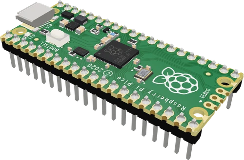
The Raspberry Pi Pico is a 51 × 21 mm board built on the RP2040: two Arm Cortex-M0+ cores at up to 133 MHz, 264 kB of SRAM and 2 MB of flash, with 26 GPIO at 3.3 V (Raspberry Pi Pico datasheet, p. 3). Power it over micro-USB or put 1.8 to 5.5 V on VSYS (p. 8), wire parts at 3.3 V logic since the pins are not 5 V tolerant, and use GP26 to GP28 for analog inputs. Hold BOOTSEL while plugging in USB to load a.uf2 file (p. 19).
The Raspberry Pi Pico is a low-cost microcontroller board built around Raspberry Pi's own RP2040 chip: a dual-core Arm Cortex-M0+ at up to 133 MHz with 264 kB of SRAM, paired on the board with 2 MB of QSPI flash (Pico datasheet, pp. 3, 4). It has no radio; the Pico W adds Wi-Fi and Bluetooth on the same pinout. The 40-pin board is 51 × 21 mm with 2.54 mm pitch through-holes and castellated edges, so it can straddle a breadboard or be soldered flat as a module (p. 6).
Of the RP2040's 30 GPIO, 26 reach the headers, all at a fixed 3.3 V; 23 are digital-only and 3 (GP26 to GP28) also feed the 12-bit, 500 ksps ADC (pp. 3, 4). The chip offers 2 UART, 2 I2C, 2 SPI and 16 PWM channels, plus two Programmable I/O blocks with 8 state machines that can bit-bang protocols such as WS2812, VGA or extra UARTs in hardware (p. 4). Four GPIO stay on the board: GP25 drives the green user LED, GP24 senses VBUS, GP29 measures VSYS/3 on ADC3 and GP23 sets the regulator's power-save mode (p. 7).
Power is flexible. USB 5 V arrives on VBUS and reaches VSYS through a Schottky diode; VSYS accepts 1.8 V to 5.5 V and feeds an RT6150 buck-boost converter that makes the board's 3.3 V (pp. 8, 20). That lets a single lithium cell or three AA cells run the Pico directly (p. 21). The board is programmed by drag and drop: hold BOOTSEL while connecting USB and it mounts as a drive that accepts.uf2 files (p. 19). C/C++ through the Pico SDK, MicroPython, CircuitPython and the Arduino core all target it.
Raspberry Pi Pico pinout
| Pin | Function | Type |
|---|---|---|
| GP0 | Digital, PWM, SPI0 RX, UART0 TX, I2C0 SDA3.3 V | bidirectional |
| GP1 | Digital, PWM, SPI0 CSn, UART0 RX, I2C0 SCL3.3 V | bidirectional |
| GND_3 | GND | power in |
| GP2 | Digital, PWM, SPI0 SCK, UART0 CTS, I2C1 SDA3.3 V | bidirectional |
| GP3 | Digital, PWM, SPI0 TX, UART0 RTS, I2C1 SCL3.3 V | bidirectional |
| GP4 | Digital, PWM, SPI0 RX, UART1 TX, I2C0 SDA3.3 V | bidirectional |
| GP5 | Digital, PWM, SPI0 CSn, UART1 RX, I2C0 SCL3.3 V | bidirectional |
| GND_8 | GND | power in |
| GP6 | Digital, PWM, SPI0 SCK, UART1 CTS, I2C1 SDA3.3 V | bidirectional |
| GP7 | Digital, PWM, SPI0 TX, UART1 RTS, I2C1 SCL3.3 V | bidirectional |
| GP8 | Digital, PWM, SPI1 RX, UART1 TX, I2C0 SDA3.3 V | bidirectional |
| GP9 | Digital, PWM, SPI1 CSn, UART1 RX, I2C0 SCL3.3 V | bidirectional |
| GND_13 | GND | power in |
| GP10 | Digital, PWM, SPI1 SCK, UART1 CTS, I2C1 SDA3.3 V | bidirectional |
| GP11 | Digital, PWM, SPI1 TX, UART1 RTS, I2C1 SCL3.3 V | bidirectional |
| GP12 | Digital, PWM, SPI1 RX, UART0 TX, I2C0 SDA3.3 V | bidirectional |
| GP13 | Digital, PWM, SPI1 CSn, UART0 RX, I2C0 SCL3.3 V | bidirectional |
| GND_18 | GND | power in |
| GP14 | Digital, PWM, SPI1 SCK, UART0 CTS, I2C1 SDA3.3 V | bidirectional |
| GP15 | Digital, PWM, SPI1 TX, UART0 RTS, I2C1 SCL3.3 V | bidirectional |
| VBUS | VBUS | power in |
| VSYS | VSYS | power in |
| GND_38 | GND | power in |
| 3V3_EN | Digital3.3 V | input |
| 3V3 | 3V33.3 V | power out |
| ADC_VREF | ADC reference3.3 V | input |
| GP28 | ADC2, Digital, PWM, SPI1 RX, UART0 TX, I2C0 SDA3.3 V | bidirectional |
| GND_33 | GND / AGND | power in |
| GP27 | ADC1, Digital, PWM, SPI1 TX, UART1 RTS, I2C1 SCL3.3 V | bidirectional |
| GP26 | ADC0, Digital, PWM, SPI1 SCK, UART1 CTS, I2C1 SDA3.3 V | bidirectional |
| RUN | Digital3.3 V | input |
| GP22 | Digital, PWM, SPI0 SCK, UART1 CTS, I2C1 SDA3.3 V | bidirectional |
| GND_28 | GND | power in |
| GP21 | Digital, PWM, SPI0 CSn, UART1 RX, I2C0 SCL3.3 V | bidirectional |
| GP20 | Digital, PWM, SPI0 RX, UART1 TX, I2C0 SDA3.3 V | bidirectional |
| GP19 | Digital, PWM, SPI0 TX, UART0 RTS, I2C1 SCL3.3 V | bidirectional |
| GP18 | Digital, PWM, SPI0 SCK, UART0 CTS, I2C1 SDA3.3 V | bidirectional |
| GND_23 | GND | power in |
| GP17 | Digital, PWM, SPI0 CSn, UART0 RX, I2C0 SCL3.3 V | bidirectional |
| GP16 | Digital, PWM, SPI0 RX, UART0 TX, I2C0 SDA3.3 V | bidirectional |
Specifications
- Microcontroller
- RP2040, dual-core Arm Cortex-M0+ at up to 133 MHzRaspberry Pi Pico datasheet, p. 3
- Memory
- 264 kB SRAM on chip; 2 MB QSPI flash on boardRaspberry Pi Pico datasheet, p. 3
- GPIO
- 26 on the headers at 3.3 V (23 digital-only, 3 ADC capable)Raspberry Pi Pico datasheet, p. 3
- ADC
- 12-bit, 500 ksps; inputs on GP26, GP27, GP28 (ADC3 reads VSYS/3)Raspberry Pi Pico datasheet, pp. 4, 7
- Peripherals
- 2 UART, 2 I2C, 2 SPI, 16 PWM channels, 2 PIO blocks with 8 state machinesRaspberry Pi Pico datasheet, p. 4
- VSYS input
- 1.8 V to 5.5 V into an RT6150 buck-boost converterRaspberry Pi Pico datasheet, pp. 8, 20
- 3V3 output
- Keep external load under 300 mARaspberry Pi Pico datasheet, p. 8
- Pin voltage limit
- IOVDD + 0.5 V (about 3.8 V on the Pico): not 5 V tolerantRP2040 datasheet, section 5.5.3.1
- Pin drive strength
- 2, 4, 8 or 12 mA selectable, 4 mA by defaultRP2040 datasheet, section 2.19.4
- Board size
- 51 × 21 mm, 1 mm thick, 2.54 mm pitchRaspberry Pi Pico datasheet, p. 6
- Logic level
- 3.3 V
- Clock speed
- 133 MHz
- Flash
- 2 MB
- RAM
- 264 KB
- GPIO pins
- 26
- ADC channels
- 3
- ADC resolution
- 12 bits
- PWM channels
- 16
- Dimensions
- 51 × 8.5 × 21 mm
- Weight
- 3 g
From the Raspberry Pi's datasheet, published by Raspberry Pi.
Common mistakes
Wiring 5 V signals straight to a GPIO
The pins are 3.3 V and limited to IOVDD + 0.5 V (RP2040 datasheet, section 5.5.3.1). A 5 V sensor output, an HC-SR04 echo or a 5 V UART TX needs a divider or a level shifter.
Putting a battery on VBUS
VBUS is the USB input. Battery and external supplies of 1.8 V to 5.5 V go on VSYS (Pico datasheet, p. 8), ideally through a Schottky diode when USB may also be connected (p. 21).
Using GP25 code on a Pico W, or W code on a Pico
On the plain Pico the green LED is GP25 (p. 7). On the Pico W it moves to the wireless chip, so LED code differs between the two boards.
Reading analog on pins that have no ADC
Only GP26, GP27 and GP28 are ADC inputs on the headers (p. 3). analogRead on any other pin returns nothing useful.
Loading 5 V I2C pull-ups onto the bus
Many I2C modules carry pull-ups to their own VCC. Powered from 5 V, they hold SDA and SCL above 3.3 V; power such modules from the Pico's 3V3 pin instead.
Raspberry Pi Pico questions
Are the Raspberry Pi Pico pins 5 V tolerant?
No. Pico IO voltage is fixed at 3.3 V (Pico datasheet, p. 3) and the RP2040 rates a pin to IOVDD + 0.5 V, about 3.8 V (RP2040 datasheet, section 5.5.3.1). Use a 1 kΩ / 2 kΩ divider or a level shifter for 5 V inputs.
Why won't my Pico show up as a drive or accept an upload?
Unplug it, hold the BOOTSEL button, plug USB back in and release: the Pico mounts as a mass storage drive and accepts a.uf2 file (Pico datasheet, p. 19). If nothing appears, try a micro-USB cable that carries data, since many are charge-only. A board that ran a crashing program may need this BOOTSEL step before the Arduino IDE can upload again.
How do I power a Raspberry Pi Pico from a battery?
Connect the battery to VSYS (pin 39), which accepts 1.8 V to 5.5 V (Pico datasheet, p. 8). A single lithium-ion cell or three AA cells in series work well; add a Schottky diode in series so the battery and USB can both be connected safely (p. 21).
Raspberry Pi Pico vs Pico W: which should I buy?
They share the RP2040, the pinout and the power system. The Pico has no radio and drives its LED from GP25 (Pico datasheet, p. 7); the Pico W adds an Infineon CYW43439 for 2.4 GHz Wi-Fi and Bluetooth. Choose the Pico W for any networked project, the Pico for everything else.
How much current can the Pico supply?
Each GPIO's drive strength is set to 2, 4, 8 or 12 mA, 4 mA by default (RP2040 datasheet, section 2.19.4). The 3V3 pin should stay under 300 mA of external load (Pico datasheet, p. 8). Heavier loads take power from VBUS or VSYS through a transistor or driver.
Which pins can I use for analog input on the Pico?
GP26, GP27 and GP28 (ADC0 to ADC2), read by a 12-bit, 500 ksps converter (Pico datasheet, pp. 3, 4). ADC3 on GP29 measures VSYS/3 inside the board (p. 7). Keep inputs within 0 V to 3.3 V and use AGND as their ground.
Raspberry Pi Pico vs Arduino Nano: what is the difference?
The Pico's RP2040 has two 133 MHz cores and 264 kB of SRAM (Pico datasheet, p. 3) and adds PIO state machines for custom interfaces, but its pins are 3.3 V. A classic Nano runs at 5 V with an 8-bit ATmega328P. Pick the Pico for speed and memory, and level-shift any 5 V parts.
Build something with the Raspberry Pi Pico
- Build this
WS2812B LED controller with PIO
Drive NeoPixel strips from a PIO state machine with precise timing and no CPU load.
- Build this
USB macro keypad
Use the RP2040's native USB to build a keyboard or macro pad with CircuitPython or the Pico SDK.
- Build this
Battery-powered data logger
Run from a lithium cell on VSYS, sample sensors on the 12-bit ADC and log to a microSD card.
- Build this
Robot or rover controller
Use the 16 PWM channels for motor drivers and servos, with MicroPython for quick iteration.
- Build this
Logic analyser or signal generator
Capture or produce fast digital signals with the PIO blocks and stream them over USB.
This page as plain Markdown, for ChatGPT, Claude or your own agent. /components/raspberry-pi-pico.md