LOLIN S2 Mini
WEMOS's D1 mini sized ESP32-S2 board: a single 240 MHz core, Wi-Fi, 4 MB flash, 2 MB PSRAM, 27 GPIOs and native USB-C in 34.3 x 25.4 mm.
- Chip and coreESP32-S2FN4R2: single-core Xtensa LX7 up to 240 MHz
- Memory320 KB SRAM, 128 KB ROM; 4 MB flash and 2 MB PSRAM in the chip package
- RadioWi-Fi 802.11 b/g/n, 2.4 GHz, PCB antenna; no Bluetooth
- I/O voltage3.3 V operating voltage; power pins allowed at most 3.6 V, so GPIOs are not 5 V tolerant
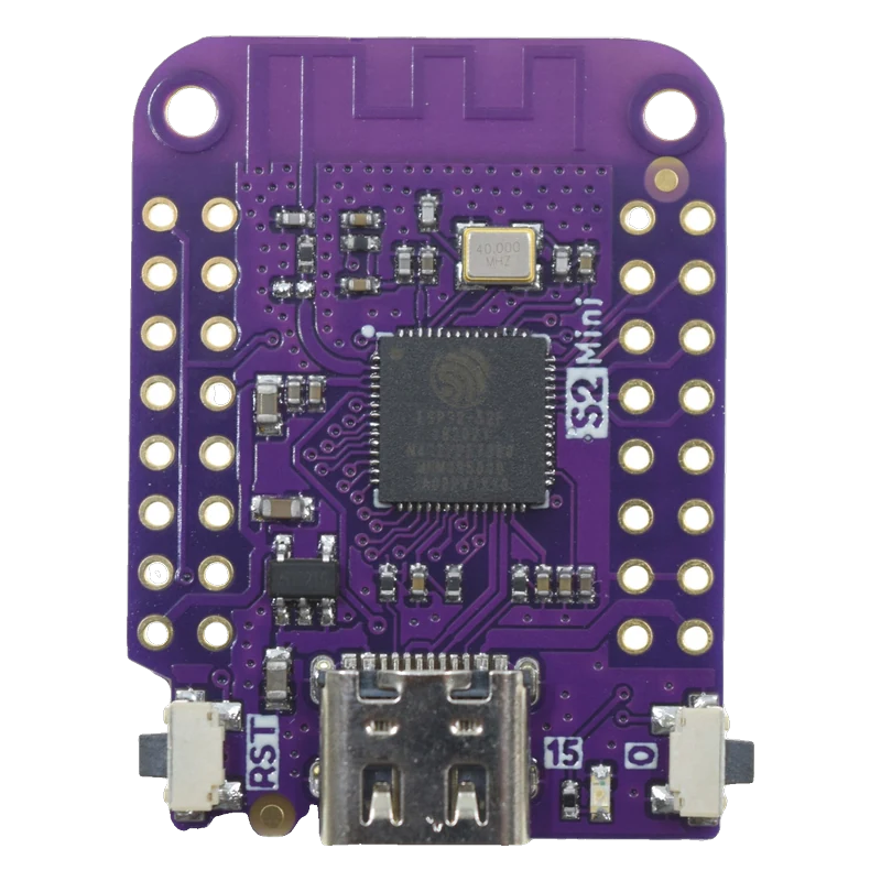
The LOLIN S2 Mini is a 34.3 x 25.4 mm board built on the ESP32-S2FN4R2: one Xtensa LX7 core at 240 MHz, Wi-Fi 802.11 b/g/n, 4 MB flash and 2 MB PSRAM in the chip, and 27 I/O pins (WEMOS S2 mini docs; ESP32-S2 datasheet v1.9, p. 3). It has no Bluetooth and no USB-serial chip: the USB-C port is the S2's own USB, so Serial needs USB CDC On Boot enabled. All pins are 3.3 V, the blue LED is on GPIO15 and the button marked 0 is GPIO0, used with RST to enter download mode.
The S2 Mini takes the D1 mini's footprint and its outer pin rows, so most LOLIN D1 mini shields still fit, and adds a second, inner row on each side for 27 usable GPIOs (WEMOS S2 mini docs). It runs MicroPython out of the box and is supported by Arduino, CircuitPython and ESP-IDF.
The ESP32-S2 is a single-core Xtensa LX7 at up to 240 MHz with 320 KB of SRAM, Wi-Fi only, and a richer analog side than most ESP32s: two 12-bit SAR ADCs on 20 channels, two 8-bit DACs on GPIO17 and GPIO18, and 14 capacitive touch inputs (ESP32-S2 datasheet v1.9, pp. 3 to 4). The FN4R2 variant puts 4 MB of flash and 2 MB of PSRAM in the chip's package.
USB-C connects directly to the S2's USB OTG pins, so the board can act as a USB keyboard, mouse, MIDI device or mass storage drive, and needs no driver. The trade-off is that a crashed sketch takes the USB port with it: hold the 0 button, tap RST and release 0 to bring up the ROM downloader again. An ME6211 LDO (500 mA class) turns USB 5 V into 3.3 V (WEMOS schematic V1.0.0).
LOLIN S2 Mini pinout
| Pin | Function | Type |
|---|---|---|
| EN | CHIP_PU, Reset3.3 V | input |
| 3 | GPIO3, ADC1_CH2, Touch 3, PWM3.3 V only | bidirectional |
| 5 | GPIO5, ADC1_CH4, Touch 5, PWM3.3 V only | bidirectional |
| 7 | GPIO7, ADC1_CH6, Touch 7, SPI SCK (LOLIN default), PWM3.3 V only | bidirectional |
| 9 | GPIO9, ADC1_CH8, Touch 9, SPI MISO (LOLIN default), PWM3.3 V only | bidirectional |
| 11 | GPIO11, ADC2_CH0, Touch 11, SPI MOSI (LOLIN default), PWM3.3 V only | bidirectional |
| 12 | GPIO12, ADC2_CH1, Touch 12, SPI SS (LOLIN default), PWM3.3 V only | bidirectional |
| 3.3V | 3.3 V3.3 V | power out |
| 1 | GPIO1, ADC1_CH0, Touch 1, PWM3.3 V only | bidirectional |
| 2 | GPIO2, ADC1_CH1, Touch 2, PWM3.3 V only | bidirectional |
| 4 | GPIO4, ADC1_CH3, Touch 4, PWM3.3 V only | bidirectional |
| 6 | GPIO6, ADC1_CH5, Touch 6, PWM3.3 V only | bidirectional |
| 8 | GPIO8, ADC1_CH7, Touch 8, PWM3.3 V only | bidirectional |
| 10 | GPIO10, ADC1_CH9, Touch 10, PWM3.3 V only | bidirectional |
| 13 | GPIO13, ADC2_CH2, Touch 13, PWM3.3 V only | bidirectional |
| 14 | GPIO14, ADC2_CH3, Touch 14, PWM3.3 V only | bidirectional |
| 40 | GPIO40, MTDO, PWM3.3 V only | bidirectional |
| 38 | GPIO38, PWM3.3 V only | bidirectional |
| 36 | GPIO36, PWM3.3 V only | bidirectional |
| 34 | GPIO34, PWM3.3 V only | bidirectional |
| 21 | GPIO21, PWM3.3 V only | bidirectional |
| 17 | GPIO17, DAC1, ADC2_CH6, PWM3.3 V only | bidirectional |
| GND | GND | passive |
| 15 | GPIO15, LED_BUILTIN, XTAL_32K_P, ADC2_CH4, PWM3.3 V only | bidirectional |
| 39 | GPIO39, MTCK, UART TX (LOLIN Serial1 default), PWM3.3 V only | bidirectional |
| 37 | GPIO37, UART RX (LOLIN Serial1 default), PWM3.3 V only | bidirectional |
| 35 | GPIO35, I2C SCL (LOLIN default), PWM3.3 V only | bidirectional |
| 33 | GPIO33, I2C SDA (LOLIN default), PWM3.3 V only | bidirectional |
| 18 | GPIO18, DAC2, ADC2_CH7, PWM3.3 V only | bidirectional |
| 16 | GPIO16, XTAL_32K_N, ADC2_CH5, PWM3.3 V only | bidirectional |
| GND | GND | passive |
| VBUS | 5 V5 V | power in |
LOLIN S2 Mini code
Every example here compiles for its board.
// LOLIN S2 Mini on LOLIN S2 Mini: wiring and a free simulation at https://www.tinkered.ai/components/lolin-s2-mini
// LOLIN S2 Mini: Wi-Fi scan, blue LED on GPIO15 blinks while scanning.
// The S2 has native USB only. This sketch prints over USB whether or not
// Tools > USB CDC On Boot is enabled. Serial Monitor at 115200.
#include <WiFi.h>

#if ARDUINO_USB_CDC_ON_BOOT
#define LOG Serial
#else
#include "USB.h"
USBCDC USBSerial;
#define LOG USBSerial
#endif

const int LED_PIN = 15;  // blue LED, HIGH = on

void setup() {
#if !ARDUINO_USB_CDC_ON_BOOT
  USB.begin();
#endif
  LOG.begin(115200);
  delay(2000);  // give the computer time to open the USB port
  pinMode(LED_PIN, OUTPUT);
  WiFi.mode(WIFI_STA);
  WiFi.disconnect();
  LOG.println("LOLIN S2 Mini Wi-Fi scan");
}

void loop() {
  digitalWrite(LED_PIN, HIGH);
  int n = WiFi.scanNetworks();
  digitalWrite(LED_PIN, LOW);
  if (n <= 0) {
    LOG.println("No networks found");
  } else {
    LOG.printf("%d networks found:\n", n);
    for (int i = 0; i < n; i++) {
      LOG.printf("%2d  %-32s  %4d dBm  ch %2d  %s\n", i + 1, WiFi.SSID(i).c_str(), (int)WiFi.RSSI(i),
                 (int)WiFi.channel(i), WiFi.encryptionType(i) == WIFI_AUTH_OPEN ? "open" : "secured");
    }
  }
  WiFi.scanDelete();
  LOG.println();
  delay(10000);
}
Before you wire it
- Enable Tools > USB CDC On Boot (or create a USBCDC port as in the sketch above) to see Serial output: the board's UART0 pins are not on USB.
- Enter download mode by hand when the port disappears: hold 0, tap RST, release 0, upload, then press RST to run.
- Keep every pin at 3.3 V or below; the S2's power pins are rated to 3.6 V at most (datasheet p. 48).
- Use ADC1 pins (GPIO1 to GPIO10) for analog readings in Wi-Fi sketches; ADC2 is shared with the Wi-Fi driver (ESP-IDF ADC oneshot guide).
- Call Wire.begin(33, 35) when you build for the generic ESP32S2 Dev Module, so I2C sits where D1 mini shields expect it.
- Never look for Bluetooth: the ESP32-S2 has Wi-Fi only.
- Never pull GPIO0 low at reset in your circuit, or the board starts the ROM downloader instead of your sketch.
- Never draw more than 40 mA from a GPIO (datasheet p. 49); drive relays and LED strips through a transistor.
- The outer rows match the D1 mini's positions; LOLIN's board definition maps I2C to GPIO33 (SDA) and GPIO35 (SCL), and SPI to GPIO7, 9, 11 and 12, so D1 mini shields line up.
- GPIO17 and GPIO18 are true 8-bit DAC outputs (datasheet p. 45): use dacWrite() for a simple analog voltage or audio tone.
- Because USB is native, the board can be a USB HID keyboard or mouse with the core's USB libraries; there is no separate serial chip to bridge.
- For battery power, feed 5 V into VBUS or a regulated 3.3 V into 3.3V (not both); the board has no charger.
Specifications
- Chip and core
- ESP32-S2FN4R2: single-core Xtensa LX7 up to 240 MHzWEMOS S2 mini docs; Espressif ESP32-S2 datasheet v1.9, p. 3
- Memory
- 320 KB SRAM, 128 KB ROM; 4 MB flash and 2 MB PSRAM in the chip packageESP32-S2 datasheet v1.9, p. 3; WEMOS S2 mini docs
- Radio
- Wi-Fi 802.11 b/g/n, 2.4 GHz, PCB antenna; no BluetoothESP32-S2 datasheet v1.9, p. 1
- I/O voltage
- 3.3 V operating voltage; power pins allowed at most 3.6 V, so GPIOs are not 5 V tolerantWEMOS S2 mini docs; ESP32-S2 datasheet v1.9, p. 48
- GPIO current
- 40 mA source, 28 mA sink typical per pin at maximum drive; 1800 mA cumulative IO output currentESP32-S2 datasheet v1.9, pp. 48 to 49
- Power
- USB-C 5 V or the VBUS pin, regulated to 3.3 V by an ME6211C33 LDO (500 mA rated); 3.3V pin is that railWEMOS S2 mini schematic V1.0.0; Microne ME6211 datasheet
- USB
- USB-C wired to the ESP32-S2's native USB OTG (GPIO19/GPIO20); no USB-serial chip, no driver neededWEMOS S2 mini schematic V1.0.0; ESP32-S2 datasheet v1.9, p. 21
- Analog
- Two 12-bit SAR ADCs, 20 channels (ADC1 on GPIO1 to 10, ADC2 on GPIO11 to 20); two 8-bit DACs on GPIO17 and GPIO18; 14 touch inputs on GPIO1 to 14ESP32-S2 datasheet v1.9, pp. 4, 21, 44 to 45
- LED and buttons
- Blue LED on GPIO15; button 0 on GPIO0; RST buttonWEMOS S2 mini pinout image V1.0.0; arduino-esp32 lolin_s2_mini pins_arduino.h
- Size
- 34.3 x 25.4 mm, 2.4 gWEMOS S2 mini docs, Technical specs
From the WEMOS LOLIN S2 mini documentation, published by WEMOS (LOLIN); ESP32-S2 by Espressif.
Common mistakes
Serial Monitor stays empty
With USB CDC On Boot disabled, Serial goes to UART0 on GPIO43 and GPIO44, which are not connected to the USB-C port. Enable USB CDC On Boot or use a USBCDC object as in the sketch.
COM port vanishes after an upload
A sketch that crashes or never starts USB leaves no port to upload to. Hold 0, tap RST, release 0: the ROM downloader appears as a new port. Upload, then press RST.
Trying to use Bluetooth libraries
BLE examples fail to compile or do nothing because the S2 has no Bluetooth radio. Use an ESP32, ESP32-S3 or ESP32-C3 board for BLE.
Shield I2C does not answer
The generic ESP32S2 board definition puts I2C on different pins from LOLIN's. Select LOLIN S2 Mini or call Wire.begin(33, 35).
LOLIN S2 Mini questions
Does the LOLIN S2 Mini have Bluetooth?
No. The ESP32-S2 has 2.4 GHz Wi-Fi only (datasheet v1.9, p. 1). For Bluetooth LE in the same size, look at an ESP32-C3 or ESP32-S3 mini board.
How do I put the S2 Mini into bootloader mode?
Hold the button marked 0 (GPIO0), press and release RST, then release 0. The chip starts its ROM downloader over USB and shows up as a new port; after uploading, press RST to run your sketch.
Does it need a CH340 or CP2102 driver?
No. The USB-C port goes straight to the ESP32-S2's own USB (WEMOS schematic V1.0.0), which every modern OS recognises without a driver.
S2 Mini or D1 mini?
Both share the 34 x 25 mm footprint and shield rows. The S2 Mini has a 240 MHz LX7, 2 MB PSRAM, 27 GPIOs, real DACs and native USB; the ESP8266 D1 mini has 11 GPIOs and a single 0 to 3.2 V analog input. The D1 mini is still simpler to recover because its USB-serial chip never disappears.
Can I read analog values while Wi-Fi is on?
Yes, on GPIO1 to GPIO10 (ADC1). ADC2 on GPIO11 to GPIO20 is also used by Wi-Fi (ESP-IDF ADC guide), so readings there can fail or be delayed.
Build something with the LOLIN S2 Mini
- Build this
USB macro keypad
Turn a few buttons into keyboard shortcuts using the S2's native USB.
- Build this
Wi-Fi touch lamp
Use a capacitive touch pin to switch an LED strip and report its state to a web page.
This page as plain Markdown, for ChatGPT, Claude or your own agent. /components/lolin-s2-mini.md