WEMOS D1 mini
A 34 × 26 mm ESP8266 Wi-Fi board with 4 MB flash, USB serial and 11 digital pins.
- ChipEspressif ESP8266EX, Tensilica L106 32-bit, 80 MHz or 160 MHz
- Flash4 MB
- Digital I/O11 pins with interrupt, PWM, I2C and one-wire (not D0)
- Analog input1 (A0), 3.2 V max through a 220 kΩ / 100 kΩ divider; 10-bit ADC
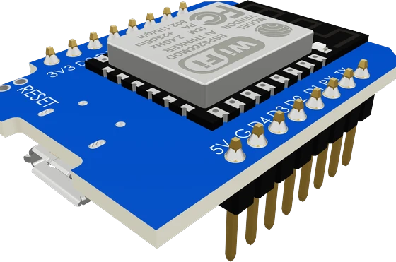
The WEMOS D1 mini is a 34.2 × 25.6 mm ESP8266 Wi-Fi board with 4 MB flash, 11 digital I/O pins and one analog input that reads up to 3.2 V (WEMOS D1 mini docs). Power it over USB or the 5V pin, wire parts at 3.3 V logic with no more than 12 mA per pin (ESP8266EX datasheet, p. 19), and use D1 (SCL) and D2 (SDA) for I2C. Keep D3 and D4 from being pulled LOW and D8 from being pulled HIGH at power-up, or it will not boot (D1 mini docs).
The D1 mini from WEMOS (later sold as LOLIN) is one of the most popular ESP8266 boards. It carries Espressif's ESP8266EX, a Tensilica L106 32-bit processor at 80 MHz or 160 MHz with 802.11 b/g/n Wi-Fi, together with 4 MB of flash, a USB-to-serial chip, a 3.3 V regulator and a reset button, on a 34.2 × 25.6 mm board weighing about 3 g (WEMOS D1 mini docs; ESP8266EX datasheet, pp. 2, 7). Version 3 uses micro-USB with a CH340C bridge and an ME6211 regulator (V3.0.0 schematic); version 4 moves to USB-C and adds a LOLIN I2C connector (V4.0.0 docs).
Two rows of eight pins carry 11 digital I/O pins, D0 to D8 plus RX and TX, one analog input A0, and power: 5V, 3V3, G and RST (D1 mini docs). The D labels map to ESP8266 GPIO numbers: D1 is GPIO5 (SCL), D2 GPIO4 (SDA), D5 to D7 GPIO14, 12 and 13 (SPI SCK, MISO, MOSI), D8 GPIO15 (SS), D3 GPIO0, D4 GPIO2 with the blue built-in LED, and D0 GPIO16. All I/O runs at 3.3 V.
A0 is the ESP8266's 10-bit ADC, which on its own reads only 0 to 1.0 V (ESP8266EX datasheet, p. 17); the board's 220 kΩ and 100 kΩ divider stretches that to 3.2 V (V3.0.0 schematic). Three pins are boot straps the board pulls to safe levels: D3 and D4 up, D8 down. D0 (GPIO16) can wake the chip from deep sleep when it is connected to RST, which the V3 board offers as a solder jumper (V3.0.0 schematic).
WEMOS D1 mini pinout
| Pin | Function | Type |
|---|---|---|
| 3V3 | 3V33.3 V | power out |
| D8 | Digital, PWM, SPI SS, strapping3.3 V | bidirectional |
| D7 | Digital, PWM, SPI MOSI3.3 V | bidirectional |
| D6 | Digital, PWM, SPI MISO3.3 V | bidirectional |
| D5 | Digital, PWM, SPI SCK3.3 V | bidirectional |
| D0 | Digital3.3 V | bidirectional |
| A0 | ADC 10-bit ADC; the board's 220k/100k divider reads 0-3.2 V3.3 V | input |
| RST | Digital3.3 V | input |
| 5V | 5V | power in |
| GND | GND (G) | power in |
| D4 | Digital, PWM, UART1 TX, strapping3.3 V | bidirectional |
| D3 | Digital, PWM, strapping3.3 V | bidirectional |
| D2 | Digital, PWM, I2C SDA (default Wire)3.3 V | bidirectional |
| D1 | Digital, PWM, I2C SCL (default Wire)3.3 V | bidirectional |
| RX | UART0 RX (the CH340's TX), Digital3.3 V | bidirectional |
| TX | UART0 TX (the CH340's RX), Digital3.3 V | bidirectional |
Specifications
- Chip
- Espressif ESP8266EX, Tensilica L106 32-bit, 80 MHz or 160 MHzWEMOS D1 mini docs; ESP8266EX datasheet v7.1, p. 7
- Flash
- 4 MBWEMOS D1 mini docs
- Digital I/O
- 11 pins with interrupt, PWM, I2C and one-wire (not D0)WEMOS D1 mini docs
- Analog input
- 1 (A0), 3.2 V max through a 220 kΩ / 100 kΩ divider; 10-bit ADCWEMOS D1 mini docs; V3.0.0 schematic; ESP8266EX datasheet, p. 17
- Logic level
- 3.3 V on all I/OWEMOS D1 mini docs
- Current per GPIO
- 12 mA maxESP8266EX datasheet v7.1, Table 5-1, p. 19
- Wi-Fi transmit current
- 170 mA typical (802.11b, +17 dBm)ESP8266EX datasheet v7.1, Table 5-3, p. 20
- Deep-sleep current (chip)
- 20 µAESP8266EX datasheet v7.1, p. 11
- USB and power (V3)
- Micro-USB, CH340C USB-UART, ME6211 3.3 V regulator, 0.5 A fuse on USB 5 VWEMOS D1 mini V3.0.0 schematic
- Size and weight
- 34.2 × 25.6 mm, 3 gWEMOS D1 mini docs
- Clock speed
- 80 MHz
- RAM
- 80 KB
- GPIO pins
- 11
- ADC channels
- 1
- ADC resolution
- 10 bits
- PWM channels
- 8
- Dimensions
- 34.3 × 25.8 × 12.9 mm
- Weight
- 3 g
- USB bridge
- CH340Cmaker's datasheet, checked 29 Oct 2026
From the WEMOS (LOLIN) / generic's datasheet, published by WEMOS (LOLIN) / generic.
Common mistakes
Using GPIO numbers and D labels interchangeably
D1 is GPIO5, not GPIO1; GPIO1 is the TX pin (D1 mini docs). In Arduino code write pinMode(D1, OUTPUT) or pinMode(5, OUTPUT), never pinMode(1, OUTPUT) for D1.
Pulling a boot pin the wrong way at power-up
A button to GND on D3 or D4 held during reset, or a pull-up on D8, stops the board from booting your sketch (D1 mini docs). Put buttons and sensors on D1, D2, D5, D6 or D7 first.
Feeding A0 more than 3.2 V
A0 is rated 3.2 V max on the D1 mini (D1 mini docs). A 5 V analog sensor output needs its own divider before A0.
Expecting the LED to light on HIGH
The built-in LED on D4 (GPIO2) is wired from 3.3 V to the pin (V3.0.0 schematic), so it lights when D4 is LOW.
Deep sleep that never wakes
ESP.deepSleep() only wakes the board when D0 (GPIO16) is connected to RST (ESP8266EX datasheet, p. 5). Without that link the board sleeps until you press reset.
WEMOS D1 mini questions
Is the WEMOS D1 mini 5 V tolerant?
No. All I/O runs at 3.3 V (D1 mini docs) and the ESP8266EX's input high limit is 3.6 V (ESP8266EX datasheet, p. 19). Use a resistor divider or a level shifter for 5 V signals. The 5V pin is a power input, not a logic level.
Which pins on the D1 mini are I2C and SPI?
I2C is D1 (GPIO5) for SCL and D2 (GPIO4) for SDA; SPI is D5 (GPIO14) SCK, D6 (GPIO12) MISO, D7 (GPIO13) MOSI and D8 (GPIO15) SS (D1 mini docs). Wire.begin() uses D2 and D1 by default in the ESP8266 Arduino core.
Why won't my D1 mini upload or show up as a port?
Use a USB cable that carries data and install the driver for the board's CH340 USB-serial chip if your computer does not see it (V3.0.0 schematic). Disconnect anything that pulls D3 or D4 LOW or D8 HIGH, since those pins set the boot mode (D1 mini docs). Garbled text after reset is the boot ROM printing at 74880 baud (ESP8266EX datasheet, p. 16), not an error.
D1 mini vs NodeMCU: which one should I use?
Both carry an ESP8266EX with 4 MB flash and use the same D-pin labels. The D1 mini is smaller at 34.2 × 25.6 mm with 11 digital pins and one analog input (D1 mini docs), while NodeMCU boards are larger and also break out some flash pins. Pick the D1 mini for compact builds and its range of stackable shields.
How many analog inputs does the D1 mini have?
One, A0, reading 0 V to 3.2 V through the board's divider (D1 mini docs; V3.0.0 schematic) with a 10-bit ADC (ESP8266EX datasheet, p. 17). For more analog channels add an I2C ADC such as an ADS1115.
D1 mini vs ESP32: what is the difference?
The D1 mini's ESP8266EX has a single 80 MHz or 160 MHz core and Wi-Fi only (D1 mini docs; ESP8266EX datasheet, p. 7). ESP32 boards add a second core, Bluetooth and many more GPIOs and ADC channels. The D1 mini remains a good fit for small Wi-Fi sensors and switches.
Build something with the WEMOS D1 mini
- Build this
Wi-Fi temperature and humidity sensor
Read a DHT22 or BME280 and report to Home Assistant, MQTT or a web page.
- Build this
Smart plug or relay switch
Switch a relay module through a transistor from a phone, with Tasmota or ESPHome firmware.
- Build this
Battery sensor with deep sleep
Wake on a timer with D0 tied to RST, send a reading, and go back to sleep.
- Build this
WS2812B LED controller
Drive an addressable LED strip with WLED and set effects from a browser.
- Build this
OLED Wi-Fi clock
Sync time over NTP and show it on a small I2C OLED on D1 and D2.
This page as plain Markdown, for ChatGPT, Claude or your own agent. /components/wemos-d1-mini.md