ESP-01S (ESP8266)
The smallest ESP8266 Wi-Fi module: 1 MB flash, two GPIOs and a UART on an 8-pin header.
- ChipEspressif ESP8266EX, Tensilica L106 32-bit, 80 MHz or 160 MHz
- Flash8 Mbit (1 MB) SPI flash
- Supply voltage3.0 V to 3.6 V, 3.3 V typical
- Supply capacity500 mA or more recommended
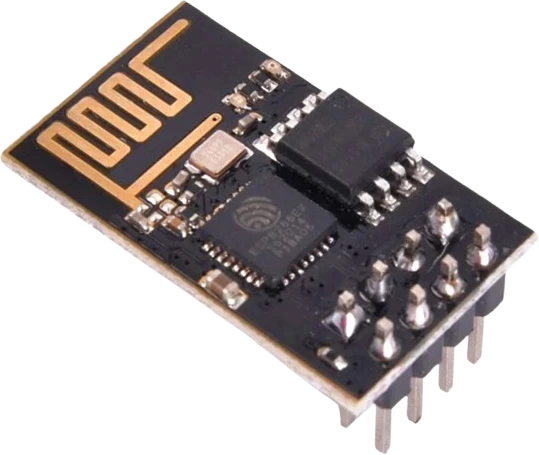
The ESP-01S is Ai-Thinker's tiny ESP8266 Wi-Fi module: an ESP8266EX with 1 MB (8 Mbit) of flash, a PCB antenna and an 8-pin header exposing VCC, GND, TX, RX, EN, RST, GPIO0 and GPIO2 (Ai-Thinker ESP-01S spec, pp. 7, 11). Power it from a 3.0 to 3.6 V supply that can deliver at least 500 mA (pp. 8, 13), connect TX and RX crossed to a 3.3 V USB-UART adapter, and hold GPIO0 LOW at reset to flash it (p. 11).
The ESP-01S is the smallest common ESP8266 module. Ai-Thinker builds it around Espressif's ESP8266EX, whose Tensilica L106 32-bit core runs at 80 MHz or 160 MHz, with 802.11 b/g/n Wi-Fi, 8 Mbit (1 MB) of SPI flash and a PCB antenna on a 24.4 × 14.4 mm board (Ai-Thinker ESP-01S spec, pp. 6, 7). It was first sold as a serial Wi-Fi adapter running AT-command firmware at 115200 baud (p. 7), and is now widely flashed with Arduino or MicroPython code to run on its own.
Its 2 × 4 header carries only power, the UART and two general-purpose pins, GPIO0 and GPIO2 (p. 11). Both are boot strapping pins: GPIO0 LOW at reset enters the download mode used for flashing, GPIO0 HIGH runs the program, and GPIO2 must be HIGH either way (p. 11). The ESP-01S pulls EN, RST and GPIO0 up on the module itself and wires its blue LED to GPIO2, where it lights when the pin is LOW (schematic, p. 12).
There is no USB, no voltage regulator and no ADC pin on the header: the chip's 10-bit ADC input is not brought out (pp. 6, 11). The module needs a clean 3.3 V supply, programs through an external USB-UART adapter, and with two GPIOs suits relay controllers, single-sensor Wi-Fi nodes and serial-to-Wi-Fi bridges.
ESP-01S (ESP8266) pinout
| Pin | Function | Type |
|---|---|---|
| GND | 1 GND | power in |
| GPIO2 | Digital, PWM, UART1 TX, strapping3.3 V | bidirectional |
| GPIO0 | Digital, PWM, strapping3.3 V | bidirectional |
| RXD | UART0 RX, Digital3.3 V | bidirectional |
| TXD | UART0 TX, Digital3.3 V | bidirectional |
| EN | Digital3.3 V | input |
| RST | Digital3.3 V | input |
| VCC | 8 VCC (3.3V) | power in |
Before you wire it
- Give it a supply of at least 500 mA; transmitting draws about 170 mA
- Supply 3.3 V only (3.0 V to 3.6 V) from a source rated for 500 mA or more (Ai-Thinker spec, pp. 8, 13): Wi-Fi transmit draws about 170 mA in bursts (p. 9). Ai-Thinker recommends an LDO, or a DC-DC converter with under 30 mV of ripple (p. 13); a 3.3 V regulator module plus a bulk capacitor close to VCC works well.
- The pins are 3.3 V logic (p. 14). A 5 V microcontroller's TX into the module's RX needs a divider or a level shifter.
- The ESP-01S pulls EN, RST and GPIO0 up on the module (schematic, p. 12). For flashing, tie GPIO0 to GND and reset; for normal running, leave GPIO0 open or HIGH (p. 11).
- GPIO0 and GPIO2 must not be held LOW by your circuit at power-up, or the module will not start your program (p. 11). Loads that pull a pin low at rest, such as some relay boards, belong behind a transistor.
- Keep the antenna end clear of metal and other boards: mount the module at the edge of a carrier with the antenna overhanging or over a cut-out (p. 13).
- Ai-Thinker suggests a 10 Ω to 100 Ω series resistor on GPIOs that leave the board, to limit overshoot and help EMI and ESD (p. 14).
- The module has its own pull-ups on EN, RST and GPIO0.
Specifications
- Chip
- Espressif ESP8266EX, Tensilica L106 32-bit, 80 MHz or 160 MHzAi-Thinker ESP-01S spec V1.0, p. 6
- Flash
- 8 Mbit (1 MB) SPI flashAi-Thinker ESP-01S spec V1.0, p. 7
- Supply voltage
- 3.0 V to 3.6 V, 3.3 V typicalAi-Thinker ESP-01S spec V1.0, p. 8
- Supply capacity
- 500 mA or more recommendedAi-Thinker ESP-01S spec V1.0, pp. 7, 13
- Transmit current
- 170 mA typical (802.11b, 11 Mbps, +17 dBm)Ai-Thinker ESP-01S spec V1.0, p. 9
- Deep-sleep current
- 20 µA typicalAi-Thinker ESP-01S spec V1.0, p. 9
- GPIO
- 2 (GPIO0, GPIO2), plus TX (GPIO1) and RX (GPIO3); 12 mA max per pinAi-Thinker ESP-01S spec V1.0, pp. 7, 8, 11
- Wi-Fi
- 802.11 b/g/n, 2400 MHz to 2483.5 MHz, PCB antennaAi-Thinker ESP-01S spec V1.0, p. 7
- Size
- 24.4 × 14.4 × 11.2 mm (height includes the pin header)Ai-Thinker ESP-01S spec V1.0, p. 7
- Operating temperature
- -20 °C to 70 °CAi-Thinker ESP-01S spec V1.0, p. 7
- Logic level
- 3.3 V
- Clock speed
- 80 MHz
- RAM
- 80 KB
- GPIO pins
- 4
- ADC channels
- 0
- PWM channels
- 4
- Weight
- 0.65 g
From the Ai-Thinker's datasheet, published by Ai-Thinker.
Common mistakes
Powering it from 5 V or a weak 3.3 V pin
VCC is rated 3.0 V to 3.6 V (Ai-Thinker spec, p. 8); 5 V damages the module. Many boards' 3.3 V pins also cannot supply the 500 mA Ai-Thinker recommends (p. 7), so the module resets as soon as Wi-Fi starts. Use a dedicated 3.3 V regulator.
Forgetting the boot strapping rules
GPIO0 LOW at reset enters download mode instead of running your code, and GPIO2 must be HIGH at reset (p. 11). A button, LED or module that pulls either pin LOW at power-up keeps the sketch from starting.
Expecting analog input or SPI
The header carries only GPIO0, GPIO2, TX and RX (p. 11). The ESP8266EX's ADC input and HSPI pins are not brought out, so analog sensors, TFT displays and SPI modules need a larger ESP8266 board such as a D1 mini or NodeMCU.
Wiring TX to TX
The module's TX goes to the adapter's RX and the module's RX to the adapter's TX, with a common ground. The adapter must use 3.3 V logic.
Treating the LED as active-high
The blue LED runs from 3.3 V to GPIO2 (schematic, p. 12), so it lights when GPIO2 is LOW. digitalWrite(2, LOW) turns it on.
ESP-01S (ESP8266) questions
How do I program an ESP-01S?
Use a USB-UART adapter set to 3.3 V: adapter TX to module RX, adapter RX to module TX, GND to GND, and a 3.3 V supply that can deliver 500 mA (Ai-Thinker spec, pp. 7, 11). Hold GPIO0 to GND while you reset or power the module to enter download mode, upload, then release GPIO0 and reset to run the sketch (p. 11). In the Arduino IDE, choose the ESP8266 core's Generic ESP8266 Module with 1 MB flash.
Why won't my ESP-01S upload or respond?
Check the supply first: brown-outs from a weak 3.3 V source are the most common cause, and Ai-Thinker asks for 500 mA or more (spec, p. 13). Then confirm TX and RX are crossed, GPIO0 is LOW during reset for flashing, and GPIO2 is not pulled LOW (p. 11). Garbage on the serial monitor right after reset is the boot ROM printing at 74880 baud with a 26 MHz crystal (ESP8266EX datasheet, p. 16), not a fault.
Can the ESP-01S run on 5 V or connect to a 5 V Arduino?
Not directly. VCC accepts 3.0 V to 3.6 V and the I/O is 3.3 V (Ai-Thinker spec, pp. 8, 14). Power it from a 3.3 V regulator and put a divider or level shifter on the Arduino's TX line into the module's RX.
What is the difference between the ESP-01 and the ESP-01S?
Both carry an ESP8266EX on the same 8-pin footprint. On the ESP-01S the blue LED is on GPIO2 and EN, RST and GPIO0 already have pull-up resistors on the module (Ai-Thinker spec, schematic p. 12), so it needs fewer external parts; the ESP-01S ships with 1 MB of flash (p. 7).
How many GPIO pins does the ESP-01S have?
Two general-purpose pins, GPIO0 and GPIO2 (Ai-Thinker spec, pp. 7, 11). RX (GPIO3) and TX (GPIO1) can also serve as GPIOs once you no longer need the serial port, and each pin is rated for 12 mA (p. 8).
Can the ESP-01S deep sleep and wake up on its own?
The chip draws about 20 µA in deep sleep (Ai-Thinker spec, p. 9), but waking from a timer needs GPIO16 wired to the reset input (ESP8266EX datasheet, p. 5), and GPIO16 is not on the ESP-01S header (spec, p. 11). Without soldering to the chip, it stays asleep until something pulls RST low.
Build something with the ESP-01S (ESP8266)
- Build this
Wi-Fi relay switch
Drive a relay through a transistor on GPIO0 or GPIO2 and switch a lamp from a phone or Home Assistant.
- Build this
Serial-to-Wi-Fi bridge
Give an Arduino or other microcontroller network access by talking to the module over its UART.
- Build this
Single-sensor MQTT node
Read a DHT22 or DS18B20 on one GPIO and publish temperature over MQTT.
- Build this
Wi-Fi NeoPixel controller
Drive a short WS2812B strip from one GPIO and set colours from a web page.
This page as plain Markdown, for ChatGPT, Claude or your own agent. /components/esp-01s.md