LOLIN D1 mini Pro
WEMOS's upgraded ESP8266 D1 mini: 16 MB flash, a lithium battery charger, an external antenna socket and a LOLIN I2C port, on the D1 mini shield layout.
- Chip and coreESP8266EX: Tensilica L106 32-bit, 80 or 160 MHz
- Memory16 MB (128 Mbit) W25Q128 flash; under 50 kB of RAM for user code with Wi-Fi in station mode
- Radio and antennaWi-Fi 802.11 b/g/n 2.4 GHz; PCB antenna by default, U.FL socket selected by moving a 0 Ω resistor (R16 to R15)
- I/O voltageAll I/O pins run at 3.3 V; ESP8266EX operating voltage 2.5 to 3.6 V. Not 5 V tolerant
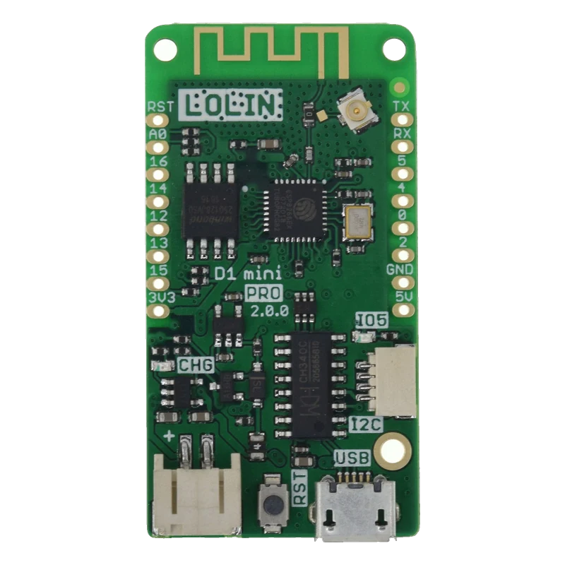
The LOLIN D1 mini Pro is an ESP8266EX board (80/160 MHz, 2.4 GHz Wi-Fi) with 16 MB of flash, 11 digital pins, one analog input that reads 0 to 3.2 V, a CH340C USB-serial chip, a TP4054 charger for a lithium cell (500 mA max) and both a PCB antenna and a U.FL socket (WEMOS D1 mini Pro docs and schematic V2.0.0). All I/O runs at 3.3 V, each pin is rated 12 mA (ESP8266EX datasheet v7.1, p. 24), and the onboard LED is on D4 (GPIO2), lit when the pin is LOW.
The Pro keeps the D1 mini's 8-pin rows and pin names, so every D1 mini shield fits, and changes what is around the ESP8266: a 128 Mbit (16 MB) W25Q128 flash instead of 4 MB, a CH340C bridge on Micro-USB, an ME6211 3.3 V regulator behind a 0.5 A fuse, and a TP4054 charger with a PH-2.0 battery connector, so a single lithium cell can power it and charge from USB (WEMOS schematic V2.0.0).
The ESP8266EX itself is a single Tensilica L106 core at 80 or 160 MHz with about 50 kB of RAM left for user programs once Wi-Fi is connected, 17 GPIOs and a 10-bit ADC (ESP8266EX datasheet v7.1, pp. 7, 13, 22). The board brings 11 of those GPIOs to the header, and divides the analog input with 220 kΩ and 100 kΩ so A0 accepts 0 to 3.2 V instead of the chip's 0 to 1 V.
Three solder jumpers change the board: one links D0 (GPIO16) to RST through 470 Ω so deep sleep can wake the chip, one routes the battery voltage to A0 through 130 kΩ, and a 0 Ω resistor selects the onboard antenna or the U.FL socket. A 4-pin SH1.0 LOLIN I2C port carries 3V3, GND, SDA (D2) and SCL (D1) for LOLIN's I2C shields (schematic V2.0.0).
LOLIN D1 mini Pro pinout
| Pin | Function | Type |
|---|---|---|
| RST | Reset3.3 V | input |
| A0 | ADC (TOUT), 0 to 3.2 V3.2 V max | input |
| D0 | GPIO16, Deep-sleep wake3.3 V only | bidirectional |
| D5 | GPIO14, SPI SCK, PWM3.3 V only | bidirectional |
| D6 | GPIO12, SPI MISO, PWM3.3 V only | bidirectional |
| D7 | GPIO13, SPI MOSI, PWM3.3 V only | bidirectional |
| D8 | GPIO15, SPI SS, PWM3.3 V only | bidirectional |
| 3V3 | 3.3 V3.3 V | power out |
| TX | GPIO1, UART0 TX3.3 V only | output |
| RX | GPIO3, UART0 RX3.3 V only | input |
| D1 | GPIO5, I2C SCL, PWM3.3 V only | bidirectional |
| D2 | GPIO4, I2C SDA, PWM3.3 V only | bidirectional |
| D3 | GPIO0, Flash mode, PWM3.3 V only | bidirectional |
| D4 | GPIO2, LED_BUILTIN, UART1 TX, PWM3.3 V only | bidirectional |
| G | GND | passive |
| 5V | 5 V5 V | power in |
LOLIN D1 mini Pro code
Every example here compiles for its board.
// LOLIN D1 mini Pro on LOLIN D1 mini Pro: wiring and a free simulation at https://www.tinkered.ai/components/lolin-d1-mini-pro
// LOLIN D1 mini Pro: Wi-Fi scan with the LED on D4 (GPIO2) lit while scanning,
// plus the A0 voltage (0 to 3.2 V range on this board). Serial Monitor at 115200.
#include <ESP8266WiFi.h>

const int LED_PIN = 2;  // D4, the onboard LED is active LOW

void setup() {
  Serial.begin(115200);
  pinMode(LED_PIN, OUTPUT);
  digitalWrite(LED_PIN, HIGH);  // off
  WiFi.mode(WIFI_STA);
  WiFi.disconnect();
  delay(100);
  Serial.println();
  Serial.println("D1 mini Pro Wi-Fi scan");
}

void loop() {
  digitalWrite(LED_PIN, LOW);  // on while scanning
  int n = WiFi.scanNetworks();
  digitalWrite(LED_PIN, HIGH);
  if (n <= 0) {
    Serial.println("No networks found");
  } else {
    Serial.printf("%d networks found:\n", n);
    for (int i = 0; i < n; i++) {
      Serial.printf("%2d  %-32s  %4d dBm  ch %2d  %s\n", i + 1, WiFi.SSID(i).c_str(), WiFi.RSSI(i),
                    WiFi.channel(i), WiFi.encryptionType(i) == ENC_TYPE_NONE ? "open" : "secured");
    }
  }
  WiFi.scanDelete();

  // A0: 10-bit reading, 1023 = about 3.2 V through the board's divider.
  int raw = analogRead(A0);
  float volts = raw * 3.2f / 1023.0f;
  Serial.printf("A0: %d (%.2f V)\n\n", raw, volts);
  delay(10000);
}
Before you wire it
- Keep D3 (GPIO0) and D4 (GPIO2) high and D8 (GPIO15) low at reset; the board's pull-ups and pull-down set this, so do not fight them with external parts.
- Keep A0 between 0 and 3.2 V (WEMOS docs); the divider is sized for that range.
- Bridge the deep-sleep jumper (D0 to RST) before using ESP.deepSleep(), or the board never wakes.
- Use a single protected 3.7 V lithium cell on the battery connector; the TP4054 charges it at up to 500 mA from USB.
- Move the 0 Ω antenna resistor to the U.FL side before fitting an external antenna (schematic V2.0.0).
- Never put 5 V on a GPIO; the ESP8266's I/O is 3.3 V.
- Never draw more than 12 mA from a pin (ESP8266EX datasheet p. 24); use a transistor for relays or LED strips.
- Never expect PWM, I2C or interrupts on D0: GPIO16 only does plain I/O and deep-sleep wake.
- D3, D4 and D8 have boot resistors on the board (pull-up, pull-up, pull-down; WEMOS docs list 10 kΩ, schematic V2.0.0 draws 12 kΩ). A button from D3 to GND works; an LED to GND on D8 can stop it booting.
- To read the battery, close the A0 battery jumper: the cell then reaches A0 through 130 kΩ, which changes the divider ratio, so calibrate against a multimeter.
- The LOLIN I2C port (SH1.0, 4 pins) carries 3V3, GND, D2 (SDA) and D1 (SCL), the same bus as the header.
- Choose a flash size of 16 MB with a filesystem partition in the board menu to use the full flash for LittleFS.
Specifications
- Chip and core
- ESP8266EX: Tensilica L106 32-bit, 80 or 160 MHzWEMOS D1 mini Pro docs, Technical specs; ESP8266EX datasheet v7.1, p. 12
- Memory
- 16 MB (128 Mbit) W25Q128 flash; under 50 kB of RAM for user code with Wi-Fi in station modeWEMOS D1 mini Pro schematic V2.0.0; ESP8266EX datasheet v7.1, p. 13
- Radio and antenna
- Wi-Fi 802.11 b/g/n 2.4 GHz; PCB antenna by default, U.FL socket selected by moving a 0 Ω resistor (R16 to R15)ESP8266EX datasheet v7.1, p. 7; WEMOS D1 mini Pro schematic V2.0.0
- I/O voltage
- All I/O pins run at 3.3 V; ESP8266EX operating voltage 2.5 to 3.6 V. Not 5 V tolerantWEMOS D1 mini Pro docs, Pin note; ESP8266EX datasheet v7.1, p. 7
- GPIO current
- 12 mA maximum drive per pin (IMAX)ESP8266EX datasheet v7.1, p. 24
- Analog input
- One 10-bit ADC on A0, 0 to 3.2 V through a 220 kΩ / 100 kΩ divider (the chip's own input is 0 to 1.0 V)WEMOS D1 mini Pro docs; schematic V2.0.0; ESP8266EX datasheet v7.1, p. 22
- Power
- Micro-USB 5 V through a 0.5 A fuse, or the 5V pin, or a lithium cell on the PH-2.0 connector; ME6211 LDO (500 mA rated) to 3.3 VWEMOS D1 mini Pro schematic V2.0.0; Microne ME6211 datasheet
- Battery charger
- TP4054 lithium charger, 500 mA maximum charging currentWEMOS D1 mini Pro docs, Features; schematic V2.0.0
- USB and LED
- CH340C USB-to-serial bridge with auto-reset; LED on D4 (GPIO2), active lowWEMOS D1 mini Pro schematic V2.0.0; docs, Pin table
- Size
- 48 x 25.4 mm, 4.5 gWEMOS D1 mini Pro docs, Technical specs
From the WEMOS LOLIN D1 mini Pro documentation, V2.0.0, published by WEMOS (LOLIN); ESP8266EX by Espressif.
Common mistakes
Board will not boot with a part on D8, D3 or D4
These are the ESP8266's boot pins. A pull-up on D8, or a module holding D3 or D4 low at power-up, sends it into the wrong mode. Move that part to D1, D2, D5, D6 or D7.
LED logic is backwards
The LED goes from 3V3 to D4 through 2 kΩ (schematic V2.0.0), so it lights when the pin is LOW. digitalWrite(LED_BUILTIN, HIGH) turns it off.
Deep sleep never wakes
Waking needs GPIO16 tied to RST. On the Pro that link is a solder jumper, open from the factory. Bridge it, and remember D0 can then no longer be used as I/O.
Weak Wi-Fi after moving the antenna link
With the 0 Ω resistor on the U.FL side, the PCB antenna is disconnected and the board needs an external antenna plugged in. Move it back for the onboard antenna.
LOLIN D1 mini Pro questions
What is the difference between the D1 mini and the D1 mini Pro?
Same pins and shields. The Pro has 16 MB of flash instead of 4 MB, a U.FL antenna socket beside the onboard antenna, a TP4054 lithium charger with a battery connector, and the LOLIN I2C port (WEMOS docs and schematic V2.0.0).
What voltage can the A0 pin read?
0 to 3.2 V. The ESP8266's own ADC input reads 0 to 1.0 V (datasheet p. 22), and the board divides A0 with 220 kΩ and 100 kΩ to stretch that to 3.2 V. analogRead() returns 0 to 1023.
Can I power the D1 mini Pro from a battery?
Yes: plug a single lithium cell into the PH-2.0 connector. The TP4054 charges it from USB at up to 500 mA, and the board runs from the cell through the ME6211 regulator when USB is unplugged (schematic V2.0.0).
Which driver do I need?
The CH340 driver from WCH; WEMOS links it on the board's page. macOS and Linux usually recognise the CH340C without extra software.
Which board should I select in Arduino?
LOLIN(WEMOS) D1 mini Pro in the ESP8266 core. It sets the 16 MB flash layout; choosing the plain D1 mini works but wastes most of the flash.
Build something with the LOLIN D1 mini Pro
- Build this
Battery weather station
Wake every 10 minutes, send temperature and humidity over Wi-Fi, then deep sleep on a lithium cell.
- Build this
Long-range Wi-Fi sensor
Use the external antenna socket to reach a router from a garden shed.
This page as plain Markdown, for ChatGPT, Claude or your own agent. /components/lolin-d1-mini-pro.md