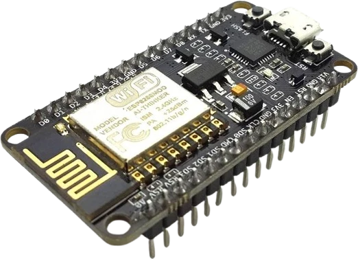
Two-wheel Arduino robot car
Drive two geared DC motors from one L298N for a differential-drive robot, using the IN pins for direction and ENA/ENB PWM for per-wheel speed.
Dual full-bridge (H-bridge) driver built on the STMicroelectronics L298 IC that lets a microcontroller run two DC motors or one bipolar stepper at up to 2A per channel.
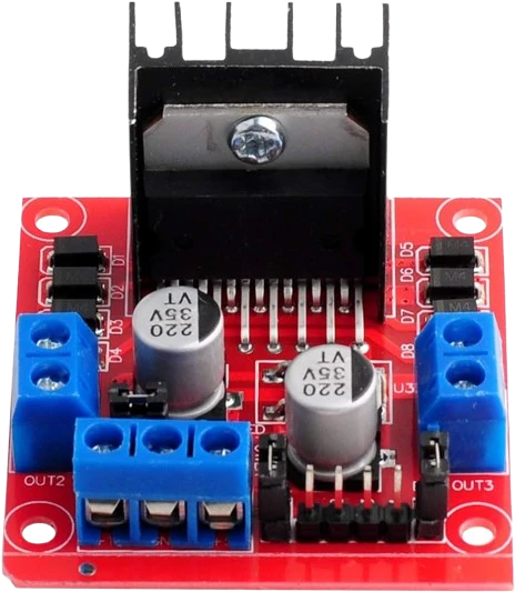
The L298N is a dual full-bridge driver based on the STMicroelectronics L298 IC. It takes low-current logic signals from a 5V microcontroller and switches the higher current and higher voltage a motor needs, well beyond what a GPIO pin can source. Each of its two H-bridges drives one DC motor in either direction, or the two bridges together drive a single bipolar stepper's two coils.
The L298 accepts a motor supply (VS) up to 46V and delivers up to 2A of continuous current per channel, with a non-repetitive peak of 3A. A separate logic supply (VSS) of 4.5 to 7V powers the internal control logic. The common breakout module adds an onboard 5V regulator so a single motor supply can also feed the logic. Direction is set with the IN pins, and speed is controlled by feeding PWM to the enable pins (ENA and ENB).
Because the output stage uses bipolar Darlington transistors, roughly 2V is dropped across the driver, so the motor sees noticeably less than the supply voltage. Under sustained load the chip dissipates real heat and relies on the module's heatsink, which is why the L298N is a workhorse for hobby robotics but not the most efficient choice for battery-critical designs.
| Pin | Function | Type |
|---|---|---|
OUT1 OUT1 | Free | Free |
OUT2 OUT2 | Free | Free |
OUT3 OUT3 | Free | Free |
OUT4 OUT4 | Free | Free |
VMS 12V / VS | Power | Power in |
GND GND | Power | Power in |
5V 5V / VSS | Power | Power in |
ENA ENA | Digital · PWM | Digital input |
IN1 IN1 | Digital | Digital input |
IN2 IN2 | Digital | Digital input |
IN3 IN3 | Digital | Digital input |
IN4 IN4 | Digital | Digital input |
ENB ENB | Digital · PWM | Digital input |
Verified from the Tinkered component library · STMicroelectronics.
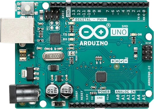
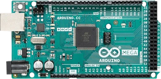
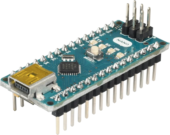
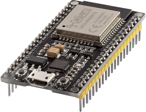
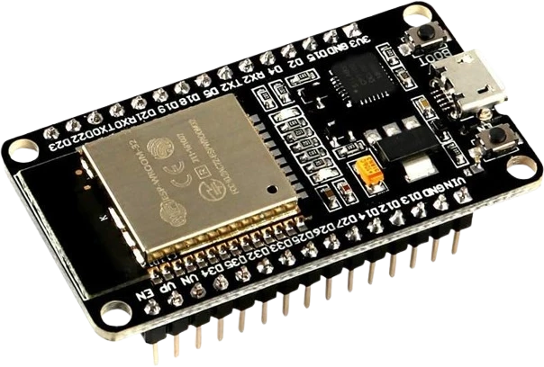
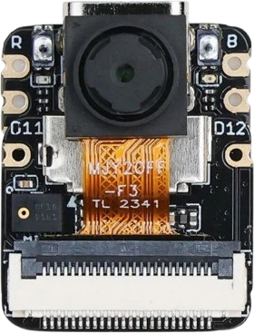
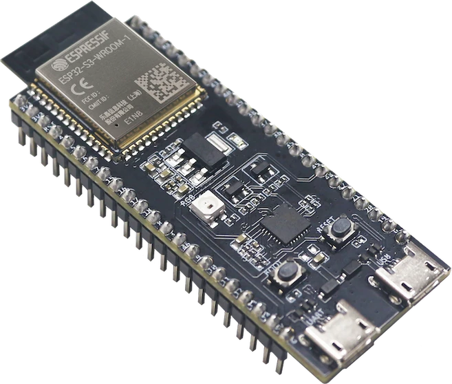
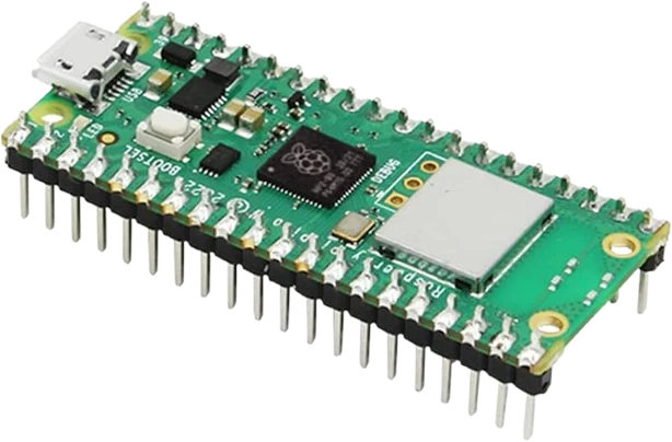
The L298N Motor Driver connects to any of the microcontrollers supported in Tinkered. Mind the 5 V logic level on 3.3 V boards.
The driver GND must connect to the microcontroller GND. Powering the motors from one supply and the logic from USB without joining the grounds leaves the IN inputs with no reference, so motors twitch, stall, or ignore commands.
The L298's Darlington output stage drops roughly 2V, so a 12V rail delivers only about 10V to the motor. If a motor seems weak, remember to size the supply above the motor's rated voltage to compensate.
Nothing moves until the enable pin for that channel is high. Use ENA and ENB for PWM speed control and the IN pins for direction. Trying to PWM the direction inputs while enable is fixed high gives poor speed control.
On the module the 5V-enable jumper lets the onboard regulator power the logic from the motor supply, but only up to about 12V. Above that, remove the jumper and supply 5V externally. Never feed 5V into the 5V pin while the jumper is still installed.
The L298 chip provides no freewheeling diodes of its own. Inductive kickback from motor coils can damage the output transistors, so add fast external diodes if your module does not already include them.
Drive two geared DC motors from one L298N for a differential-drive robot, using the IN pins for direction and ENA/ENB PWM for per-wheel speed.
Wire a NEMA-17 or similar bipolar stepper's two coils across the two bridges (OUT1/OUT2 and OUT3/OUT4) to step the motor for positioning and CNC-style projects.
Run a single DC motor through one bridge and vary its speed with PWM on the enable pin for adjustable cooling fans, water pumps, or conveyors.
Use one H-bridge to reverse a DC gearmotor on demand, giving open/close or forward/back control for doors, blinds, and small conveyors.
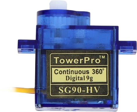
servo-sg90Compact positional servo
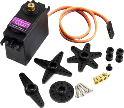
servo-mg996r-straightHigh-torque servo variant
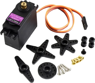
servo-mg996r-crossHigh-torque servo variant
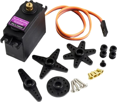
servo-mg996r-starHigh-torque servo variant
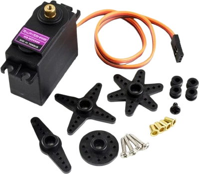
servo-mg996r-roundHigh-torque servo variant
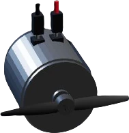
dc-motorBrushed direct-current motor
Drop the L298N Motor Driver into a circuit, write firmware, and simulate it in your browser, then deploy to real hardware. All in one editable Tinkered project.