L293D Motor Driver IC
A 16-pin DIP with two H-bridges and built-in clamp diodes that drives two DC motors forward and reverse at 600 mA each.
- Motor supply (VCC2)4.5 V to 36 V, never below VCC1
- Logic supply (VCC1)4.5 V to 7 V recommended (5 V ± 0.5 V)
- Output current600 mA continuous per channel, 1.2 A peak (t ≤ 100 µs)
- Input high threshold2.3 V min; inputs tolerate up to 7 V
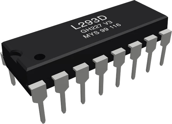
The L293D is a quadruple half-H driver in a 16-pin DIP: paired into two H-bridges, it drives two DC motors (or one bipolar stepper) at up to 600 mA per channel from a 4.5 V to 36 V motor supply, with the clamp diodes built in (TI L293D datasheet SLRS008D, pp. 1, 4). Feed 5 V logic to VCC1 (pin 16), the motor supply to VCC2 (pin 8) and ground to pins 4, 5, 12 and 13; set direction with IN1/IN2 and IN3/IN4 and PWM the enable pins (1 and 9) for speed (p. 3). Inputs read high from 2.3 V, so 3.3 V boards drive it directly (p. 4).
The L293D contains four half-H drivers, each a totem-pole output with a Darlington sink and a pseudo-Darlington source, enabled in pairs: 1,2EN controls drivers 1 and 2, 3,4EN controls drivers 3 and 4 (TI L293D datasheet SLRS008D, p. 7). Wired as pairs, they form two full H-bridges, each able to run one brushed DC motor in both directions, or together one bipolar stepper motor. The D in the name means the output clamp diodes for inductive loads are integrated on the chip, so a motor needs no external flyback diodes (p. 7).
Each channel is rated for 600 mA continuous and 1.2 A peak for pulses of 100 µs or less (p. 4). The chip has two supplies: VCC1 (pin 16) powers the internal logic at 4.5 V to 7 V, and VCC2 (pin 8) powers the motors from VCC1 up to 36 V (p. 4). The inputs are TTL compatible and tolerate up to 7 V, and anything above 2.3 V reads high (pp. 4, 7), so a 3.3 V ESP32 or Raspberry Pi Pico can drive the inputs while VCC1 stays on 5 V.
Direction comes from the two inputs of a bridge and speed from its enable pin. With the enable high, each output follows its input; with the enable low, both outputs go to high impedance and the motor coasts (pp. 8, 11). Because the outputs are bipolar transistors, they drop voltage: at 600 mA the high side sits 1.4 V typical (1.8 V max) below VCC2 and the low side 1.2 V typical (1.8 V max) above ground (p. 5), so a motor sees roughly 2.6 V less than the motor supply. The four GND pins double as the heat sink and belong on a generous copper area (pp. 3, 13).
L293D Motor Driver IC pinout
| Pin | Function | Type |
|---|---|---|
| EN1 | Digital, PWM | input |
| IN1 | Digital | input |
| OUT1 | Digital | free |
| GND | 4 GND | power in |
| GND_2 | 5 GND | power in |
| OUT2 | Digital | free |
| IN2 | Digital | input |
| VCC2 | 8 VCC2 (motor supply, 4.5-36 V)VCC1 to 36 V (motors) | power in |
| EN2 | Digital, PWM | input |
| IN3 | Digital | input |
| OUT3 | Digital | free |
| GND_3 | 12 GND | power in |
| GND_4 | 13 GND | power in |
| OUT4 | Digital | free |
| IN4 | Digital | input |
| VCC1 | 16 VCC1 (5 V logic)4.5 to 7 V (logic) | power in |
How to wire the L293D Motor Driver IC
Pin by pin, for the board you have.
| L293D Motor Driver IC | Arduino Uno | Note |
|---|---|---|
| EN1 | D9 | |
| IN1 | D2 | |
| IN2 | D3 | |
| EN2 | D10 | |
| IN3 | D4 | |
| IN4 | D5 | |
| VCC1 | 5V | |
| GND | GND |
| L293D Motor Driver IC | ESP32 DevKit V1 | Note |
|---|---|---|
| EN1 | GPIO13 (D13) | |
| IN1 | GPIO14 (D14) | |
| IN2 | GPIO27 (D27) | |
| EN2 | GPIO4 (D4) | |
| IN3 | GPIO26 (D26) | |
| IN4 | GPIO25 (D25) | |
| VCC1 | VIN | |
| GND | GND |
- VCC1 is on VIN, which gives about 5 V only while the board is powered from USB.
| L293D Motor Driver IC | Raspberry Pi Pico | Note |
|---|---|---|
| EN1 | GP0 | |
| IN1 | GP1 | |
| IN2 | GP2 | |
| EN2 | GP3 | |
| IN3 | GP4 | |
| IN4 | GP5 | |
| VCC1 | VBUS | |
| GND | GND |
- VCC1 is on VBUS, which gives about 5 V only while the board is powered from USB.
L293D Motor Driver IC code
Every example here compiles for its board.
// L293D Motor Driver IC on Arduino Uno: wiring and a free simulation at https://www.tinkered.ai/components/l293d-motor-driver
const int EN1 = 9,  IN1 = 2, IN2 = 3;   // channel 1 (motor A)
const int EN2 = 10, IN3 = 4, IN4 = 5;   // channel 2 (motor B)

void setup() {
  const int pins[] = {EN1, IN1, IN2, EN2, IN3, IN4};   // an array: AVR has no <initializer_list>
  for (int p : pins) pinMode(p, OUTPUT);
}

// speed: -255..255, its sign the direction
void drive(int en, int inA, int inB, int speed) {
  digitalWrite(inA, speed > 0);
  digitalWrite(inB, speed < 0);
  analogWrite(en, abs(speed));
}

void loop() {
  drive(EN1, IN1, IN2, 200);  drive(EN2, IN3, IN4, 200);  delay(2000);   // both forward
  drive(EN1, IN1, IN2, 0);    drive(EN2, IN3, IN4, 0);    delay(1000);   // stop
  drive(EN1, IN1, IN2, -200); drive(EN2, IN3, IN4, 200);  delay(2000);   // spin in place
  drive(EN1, IN1, IN2, 0);    drive(EN2, IN3, IN4, 0);    delay(1000);
}
// L293D Motor Driver IC on ESP32 DevKit V1: wiring and a free simulation at https://www.tinkered.ai/components/l293d-motor-driver
const int EN1 = 13,  IN1 = 14, IN2 = 27;   // channel 1 (motor A)
const int EN2 = 4, IN3 = 26, IN4 = 25;   // channel 2 (motor B)

void setup() {
  const int pins[] = {EN1, IN1, IN2, EN2, IN3, IN4};   // an array: AVR has no <initializer_list>
  for (int p : pins) pinMode(p, OUTPUT);
}

// speed: -255..255, its sign the direction
void drive(int en, int inA, int inB, int speed) {
  digitalWrite(inA, speed > 0);
  digitalWrite(inB, speed < 0);
  analogWrite(en, abs(speed));
}

void loop() {
  drive(EN1, IN1, IN2, 200);  drive(EN2, IN3, IN4, 200);  delay(2000);   // both forward
  drive(EN1, IN1, IN2, 0);    drive(EN2, IN3, IN4, 0);    delay(1000);   // stop
  drive(EN1, IN1, IN2, -200); drive(EN2, IN3, IN4, 200);  delay(2000);   // spin in place
  drive(EN1, IN1, IN2, 0);    drive(EN2, IN3, IN4, 0);    delay(1000);
}
// L293D Motor Driver IC on Raspberry Pi Pico: wiring and a free simulation at https://www.tinkered.ai/components/l293d-motor-driver
const int EN1 = 0,  IN1 = 1, IN2 = 2;   // channel 1 (motor A)
const int EN2 = 3, IN3 = 4, IN4 = 5;   // channel 2 (motor B)

void setup() {
  const int pins[] = {EN1, IN1, IN2, EN2, IN3, IN4};   // an array: AVR has no <initializer_list>
  for (int p : pins) pinMode(p, OUTPUT);
}

// speed: -255..255, its sign the direction
void drive(int en, int inA, int inB, int speed) {
  digitalWrite(inA, speed > 0);
  digitalWrite(inB, speed < 0);
  analogWrite(en, abs(speed));
}

void loop() {
  drive(EN1, IN1, IN2, 200);  drive(EN2, IN3, IN4, 200);  delay(2000);   // both forward
  drive(EN1, IN1, IN2, 0);    drive(EN2, IN3, IN4, 0);    delay(1000);   // stop
  drive(EN1, IN1, IN2, -200); drive(EN2, IN3, IN4, 200);  delay(2000);   // spin in place
  drive(EN1, IN1, IN2, 0);    drive(EN2, IN3, IN4, 0);    delay(1000);
}
Before you wire it
- Two supplies, both wired. VCC1 (pin 16) is the logic: 5 V (4.5-7 V), from the MCU's 5V, also on an ESP32 or a Pico (their 3.3 V outputs are valid HIGH inputs: VIH 2.3 V). VCC2 (pin 8) is the motors' supply (4.5-36 V). Without either, the motors do not turn.
- Ground: wire GND (pin 4) to the MCU's GND; the four GND pins are one (the chip's lead frame and heat sink). A separate motor supply shares this ground.
- The chip drops about 2.6 V typical: a motor sees about VCC2 - 2.6 V.
- One motor per channel, across that channel's two outputs (OUT1/OUT2 or OUT3/OUT4).
- For speed control, wire EN1/EN2 to PWM pins (Uno: D3, D5, D6, D9, D10, D11; ESP32: any LEDC pin).
- No motor straight on a GPIO: it goes across the L293D's outputs.
- No VCC1 above 7 V (it destroys the chip) and no motor supply on VCC1: the motor supply goes on VCC2.
- No IN1 and IN2 both HIGH expecting motion: that is a brake.
- No analogWrite on the IN pins for speed: PWM the enable.
- Wire both supplies. VCC1 (pin 16) takes the 5 V logic supply, 4.5 V to 7 V; VCC2 (pin 8) takes the motor supply, from VCC1 up to 36 V (TI datasheet, p. 4). Never put a motor battery above 7 V on VCC1.
- Join all grounds: pins 4, 5, 12 and 13 are the chip's ground and heat sink (p. 3), and the motor supply's negative must meet the microcontroller's GND there.
- Place a bypass capacitor of 0.1 µF or more from VCC1 to GND and from VCC2 to GND, close to the chip (p. 13). A larger electrolytic on VCC2 helps absorb motor current spikes.
- Put one motor across each bridge: OUT1/OUT2 (pins 3 and 6) or OUT3/OUT4 (pins 11 and 14). The clamp diodes are built in (p. 7), so no external flyback diodes are needed.
- PWM the enable pins (1 and 9) for speed and use IN1/IN2 and IN3/IN4 for direction. Enable low lets the motor coast; both inputs equal with the enable high is a fast stop (p. 11).
- Budget for the drop: about 1.4 V on the high side and 1.2 V on the low side at 600 mA, typical (p. 5). Give VCC2 roughly the motor's rated voltage plus 2.5 V, for example 9 V for a 6 V motor.
- Watch heat: at 36.4 °C/W (p. 4), every watt the chip dissipates raises the junction about 36 °C. Two motors near 600 mA each get the chip hot; solder the GND pins to a large copper area on a PCB (p. 13).
Specifications
- Motor supply (VCC2)
- 4.5 V to 36 V, never below VCC1TI L293D datasheet SLRS008D, pp. 1, 4
- Logic supply (VCC1)
- 4.5 V to 7 V recommended (5 V ± 0.5 V)TI L293D datasheet SLRS008D, pp. 4, 13
- Output current
- 600 mA continuous per channel, 1.2 A peak (t ≤ 100 µs)TI L293D datasheet SLRS008D, p. 4
- Input high threshold
- 2.3 V min; inputs tolerate up to 7 VTI L293D datasheet SLRS008D, pp. 4, 7
- Output voltage drop at 600 mA
- High side VCC2 - 1.4 V typ (- 1.8 V max); low side 1.2 V typ (1.8 V max)TI L293D datasheet SLRS008D, p. 5
- Clamp diodes
- Integrated on every outputTI L293D datasheet SLRS008D, pp. 1, 7
- Logic supply current
- 35 mA typ, 60 mA max (all outputs low)TI L293D datasheet SLRS008D, p. 5
- Thermal resistance
- 36.4 °C/W junction to ambient (PDIP-16); TJ max 150 °CTI L293D datasheet SLRS008D, p. 4
- Operating temperature
- 0 °C to 70 °CTI L293D datasheet SLRS008D, p. 4
- Pinout (PDIP-16)
- 1 1,2EN; 2 1A; 3 1Y; 4, 5, 12, 13 GND; 6 2Y; 7 2A; 8 VCC2; 9 3,4EN; 10 3A; 11 3Y; 14 4Y; 15 4A; 16 VCC1TI L293D datasheet SLRS008D, p. 3
- Interface
- GPIO
- Dimensions
- 19.3 × 7.62 × 6.8 mm
- Weight
- 1 g
From the Texas Instruments / STMicroelectronics's datasheet, published by Texas Instruments / STMicroelectronics.
Common mistakes
Powering the motors from VCC1
VCC1 (pin 16) is only the logic supply, rated 4.5 V to 7 V (TI datasheet, p. 4). The motor supply goes on VCC2 (pin 8). With VCC2 left unconnected, the outputs have nothing to drive the motors with.
Forgetting the drop across the bridge
The bipolar outputs lose about 2.6 V together at 600 mA, typical (p. 5). A 5 V motor on a 5 V VCC2 crawls. Raise VCC2 above the motor's rating.
Using PWM on the IN pins for speed
Speed control belongs on the enable pins. PWM on an IN pin works only with careful timing, and setting both IN pins high gives a fast stop, not full speed (p. 11).
No common ground
With a separate motor battery, its negative must connect to the microcontroller's GND and the L293D's GND pins; otherwise the inputs have no reference and the motors twitch or do nothing.
Asking more than 600 mA
600 mA is the continuous limit per channel and 1.2 A is only a 100 µs peak (p. 4). Motors that stall at 1 A or more overheat the chip; pick a larger driver such as the TB6612FNG or L298N for them.
L293D Motor Driver IC questions
What is the difference between the L293D and the L298N?
The L293D handles 600 mA per channel (1.2 A peak) up to 36 V and has its clamp diodes built in, in a breadboard-friendly DIP-16 (TI L293D datasheet, pp. 1, 4). The L298 behind the L298N module handles 2 A per channel up to 46 V but needs external fast diodes, which the module provides, and drops 1.8 V to 3.2 V at 1 A (ST L298 datasheet, pp. 2, 3, 7). Choose the L293D for small hobby motors and the L298N for larger ones.
Can I use the L293D with an ESP32 or a 3.3 V board?
Yes. Its inputs read high from 2.3 V (TI datasheet, p. 4), so 3.3 V GPIOs drive IN and EN pins directly. VCC1 still needs 4.5 V to 7 V, so take it from the board's 5 V or VIN pin, not 3.3 V.
How much current can the L293D supply?
600 mA continuous per channel and 1.2 A for non-repetitive pulses of 100 µs or less (TI datasheet, p. 4). Small yellow TT gear motors fit comfortably; anything that stalls above 600 mA needs a bigger driver.
Why does my motor run slowly or not at all with the L293D?
Check that VCC2 (pin 8) has the motor supply and VCC1 (pin 16) has 5 V, that the grounds are shared, and that the enable pin is high or receiving PWM. Then allow for the output drop of about 1.4 V high side plus 1.2 V low side at 600 mA, typical (TI datasheet, p. 5): a 6 V supply leaves a motor about 3.4 V.
Does the L293D need flyback diodes?
No. The L293D integrates the output clamp diodes for inductive transient suppression; it is the plain L293 that needs external diodes (TI datasheet, p. 7).
How do I brake or coast a motor with the L293D?
With the enable high, setting both inputs of a bridge to the same level stops the motor fast; setting the enable low turns the outputs off and lets it coast (TI datasheet, pp. 8, 11). IN1 high with IN2 low turns it one way, the reverse turns it the other.
Can the L293D drive a stepper motor?
Yes, a bipolar stepper whose coils draw 600 mA or less: one coil across each bridge, stepped with the four inputs (TI datasheet, p. 1 lists stepper drivers among its applications). Check the coil current on the motor's label first: many NEMA 17 steppers draw well over 600 mA per coil.
Build something with the L293D Motor Driver IC
- Build this
Two-wheel robot car
Drive the left and right gear motors forward, back and in turns from four GPIOs and two PWM pins.
- Build this
Line-following robot
Steer by adjusting each motor's PWM speed from IR line sensors.
- Build this
Bluetooth-controlled rover
Pair an HC-05 with the L293D and steer the car from a phone app.
- Build this
Bipolar stepper control
Run a small bipolar stepper by energising its two coils in sequence through the two bridges.
- Build this
Motorised blinds or door
Open and close with one DC motor, end-stop switches and a timer.
This page as plain Markdown, for ChatGPT, Claude or your own agent. /components/l293d-motor-driver.md