L293D Motor Driver IC with an ESP32 DevKit V1
A 16-pin DIP with two H-bridges and built-in clamp diodes that drives two DC motors forward and reverse at 600 mA each.
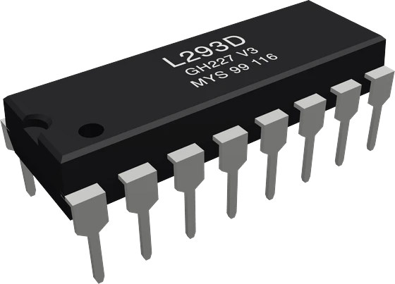
On the ESP32 DevKit V1 the L293D's logic supply VCC1 goes to VIN for its 4.5 V to 7 V range, while its inputs read the ESP32's 3.3 V signals as high because their threshold is only 2.3 V. The two enables take PWM on GPIO13 and GPIO4, and the four direction inputs sit on GPIO14, GPIO27, GPIO26 and GPIO25.
Wiring the L293D Motor Driver IC to the ESP32 DevKit V1
Pin by pin.
| L293D Motor Driver IC | ESP32 DevKit V1 |
|---|---|
| EN1 | GPIO13 (D13) |
| IN1 | GPIO14 (D14) |
| IN2 | GPIO27 (D27) |
| EN2 | GPIO4 (D4) |
| IN3 | GPIO26 (D26) |
| IN4 | GPIO25 (D25) |
| VCC1 | VIN |
| GND | GND |
- VCC1 is on VIN, which gives about 5 V only while the board is powered from USB.
What to know on the ESP32 DevKit V1
- VCC1 cannot go on 3V3: the logic supply is rated 4.5 V to 7 V. VIN gives about 5 V only while the DevKit runs from USB, so on a battery build feed VCC1 from a 5 V rail of its own.TI L293D datasheet SLRS008D, pp. 4, 13
- No level shifting is needed in this direction: the inputs need 2.3 V minimum for a high and tolerate up to 7 V, and an ESP32 output gives at least 0.8 x VDD.TI L293D datasheet SLRS008D, pp. 4, 7; Espressif ESP32 Series Datasheet v5.3, p. 52
- analogWrite() on EN1 and EN2 runs on the ESP32's LED PWM controller, which has sixteen PWM generators that can be routed to any GPIO; GPIO34 to GPIO39 are input-only and cannot drive an enable.Espressif ESP32 Series Datasheet v5.3, p. 39; Espressif ESP32 Series Datasheet v5.3, p. 61
- The motors run from VCC2 (4.5 V to 36 V) on their own supply, never from the DevKit. The chip's logic alone draws 35 mA typical, 60 mA maximum, from VIN.TI L293D datasheet SLRS008D, pp. 1, 4, 5
L293D Motor Driver IC code for the ESP32 DevKit V1
Compiled for esp32:esp32:esp32 on 2026-10-29.
// L293D Motor Driver IC on ESP32 DevKit V1: wiring and a free simulation at https://www.tinkered.ai/components/l293d-motor-driver/esp32
const int EN1 = 13,  IN1 = 14, IN2 = 27;   // channel 1 (motor A)
const int EN2 = 4, IN3 = 26, IN4 = 25;   // channel 2 (motor B)

void setup() {
  const int pins[] = {EN1, IN1, IN2, EN2, IN3, IN4};   // an array: AVR has no <initializer_list>
  for (int p : pins) pinMode(p, OUTPUT);
}

// speed: -255..255, its sign the direction
void drive(int en, int inA, int inB, int speed) {
  digitalWrite(inA, speed > 0);
  digitalWrite(inB, speed < 0);
  analogWrite(en, abs(speed));
}

void loop() {
  drive(EN1, IN1, IN2, 200);  drive(EN2, IN3, IN4, 200);  delay(2000);   // both forward
  drive(EN1, IN1, IN2, 0);    drive(EN2, IN3, IN4, 0);    delay(1000);   // stop
  drive(EN1, IN1, IN2, -200); drive(EN2, IN3, IN4, 200);  delay(2000);   // spin in place
  drive(EN1, IN1, IN2, 0);    drive(EN2, IN3, IN4, 0);    delay(1000);
}
L293D Motor Driver IC on the ESP32 DevKit V1: questions
Can an ESP32 drive an L293D directly?
Yes. The L293D reads 2.3 V as a high (TI datasheet, p. 4), so the ESP32's 3.3 V outputs drive EN and IN directly. Only VCC1 needs 5 V, from VIN or another 5 V rail.
Why do my motors not turn with the ESP32 on battery?
VIN carries about 5 V only from USB, so VCC1 loses its supply. Give the L293D's VCC1 its own 5 V and VCC2 the motor supply, with grounds joined.
Keep going
This guide as plain Markdown. /components/l293d-motor-driver/esp32.md