L293D vs L298N
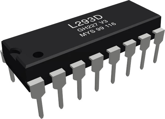
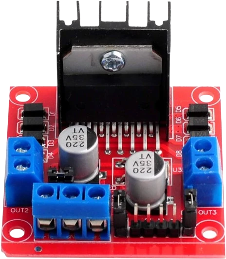
Motor current decides: the L293D carries 600 mA per channel (1.2 A for 100 µs pulses) and has its clamp diodes on the chip (TI L293D datasheet SLRS008D, pp. 1, 4), while the L298 on the L298N module carries 2 A DC per channel (ST L298 datasheet, p. 2). Both are bipolar H-bridges that lose voltage to the motor: about 2.6 V typical at 600 mA on the L293D (TI, p. 5) and 1.8 V to 3.2 V at 1 A on the L298 (ST, p. 3). Use the L293D for small gear motors on a breadboard and the L298N for motors that draw more than 600 mA.
Side by side
| L293D | L298N | |
|---|---|---|
| FormTI L293D datasheet SLRS008D, p. 3; Handson Technology L298N user guide, p. 3 | 16-pin DIP chip, fits a breadboard | 43 × 43 mm module with screw terminals and heatsink |
| Current per channelTI L293D datasheet SLRS008D, p. 4; ST L298 datasheet, p. 2 | 600 mA continuous, 1.2 A peak (100 µs) | 2 A DC, 2.5 A repetitive peak, 3 A for 100 µs |
| Motor supplyTI L293D datasheet SLRS008D, p. 4; ST L298 datasheet, p. 3; Handson L298N user guide, p. 1 | 4.5 V to 36 V (VCC2, never below VCC1) | Up to 46 V on the L298; 5 V to 35 V on the module |
| Logic supplyTI L293D datasheet SLRS008D, p. 4; ST L298 datasheet, p. 3 | 4.5 V to 7 V (VCC1) | 4.5 V to 7 V (VSS), or the module's on-board 5 V regulator |
| Voltage lost in the bridgeTI L293D datasheet SLRS008D, p. 5; ST L298 datasheet, p. 3 | About 2.6 V typ at 600 mA (1.4 V high side, 1.2 V low side) | 1.8 V to 3.2 V at 1 A, up to 4.9 V at 2 A |
| Flyback diodesTI L293D datasheet SLRS008D, p. 7; ST L298 datasheet, p. 7; Handson L298N user guide, p. 1 | Integrated on every output | None in the chip; the module carries them |
| Input high levelTI L293D datasheet SLRS008D, p. 4; ST L298 datasheet, p. 3 | 2.3 V min, so 3.3 V boards drive it | 2.3 V min, so 3.3 V boards drive it |
| Logic supply currentTI L293D datasheet SLRS008D, p. 5; ST L298 datasheet, p. 3 | 35 mA typ, 60 mA max | 24 mA typ, 36 mA max |
| Control pinsTI L293D datasheet SLRS008D, p. 3; ST L298 datasheet, p. 3 | 1,2EN and 3,4EN for PWM; 1A to 4A for direction | ENA and ENB for PWM; IN1 to IN4 for direction |
Which one to pick
- Small TT gear motors and other loads that stay under 600 mA per channel (TI L293D datasheet, p. 4).
- Breadboard prototypes and custom PCBs: one 16-pin DIP with the clamp diodes built in, no external parts but bypass capacitors (pp. 1, 7, 13).
- Cheap, compact builds where a 43 mm module with a heatsink does not fit.
- Motors that draw between 600 mA and 2 A per channel (ST L298 datasheet, p. 2).
- Robot chassis wired with screw terminals, where the module's diodes, heatsink and 5 V regulator save building a board.
- Motor supplies above 36 V on the bare L298, which goes to 46 V (ST, p. 3).
Swapping one for the other
What changes in the wiring and the code.
- The control logic is the same: two direction inputs and one enable per bridge. L293D 1A/2A and 1,2EN map to the L298N's IN1/IN2 and ENA; 3A/4A and 3,4EN map to IN3/IN4 and ENB. Sketches that drive those pins run unchanged.
- Supplies change: the L293D needs 5 V on VCC1 (pin 16) and the motor supply on VCC2 (pin 8) (TI, p. 4). The L298N module takes the motor supply on its 12V terminal and, with its 5V jumper fitted, makes its own logic supply; remove the jumper before feeding 5 V from the board.
- Diodes: the L293D has them on the chip (TI, p. 7). A bare L298 needs fast-recovery diodes with trr of 200 ns or less on every output (ST, p. 7); the red module already carries them.
- Both drop several volts, so keep the motor supply about 2 V to 3 V above the motor's rating whichever you use (TI, p. 5; ST, p. 3).
L293D or L298N: questions
Is the L298N more powerful than the L293D?
Yes. The L298 is rated 2 A DC per channel (ST L298 datasheet, p. 2) against the L293D's 600 mA continuous (TI L293D datasheet, p. 4). Neither is efficient: both use bipolar transistors that turn a few volts into heat at full current.
Can I use the L293D instead of the L298N?
Only for motors that stay under 600 mA per channel; 1.2 A is allowed only for 100 µs pulses (TI L293D datasheet, p. 4). The input and enable logic is the same, so the code carries over, but the supplies are wired differently: 5 V on VCC1 and the motor supply on VCC2.
Do both work with an ESP32 or Raspberry Pi Pico?
Yes. Both read an input as high from 2.3 V (TI L293D datasheet, p. 4; ST L298 datasheet, p. 3), so 3.3 V GPIOs drive them directly. The logic supply of either chip still needs 4.5 V to 7 V, so take it from the board's 5 V pin or the module's regulator.
Why is my motor slower than its rated speed on either driver?
Both bridges lose voltage: the L293D about 1.4 V on the high side and 1.2 V on the low side at 600 mA, typical (TI, p. 5), the L298 1.8 V to 3.2 V at 1 A (ST, p. 3). A 6 V motor on a 6 V supply sees only 3 V to 4 V. Raise the supply, or use a MOSFET driver such as the TB6612FNG for low-voltage motors.
Which one can drive a NEMA 17 stepper?
The L298N, for a stepper whose coils draw up to 2 A (ST L298 datasheet, p. 2), with the caveat that it has no current limiting, so the supply voltage must suit the coil resistance. The L293D only suits steppers whose coils draw 600 mA or less (TI, p. 4). For most NEMA 17 motors a current-limiting driver such as the A4988 is the better fit.
The two references
Checked on 2026-10-29 against 3 sources, the makers’ datasheets first.
This comparison as plain Markdown. /compare/l293d-motor-driver-vs-l298n-stepper-driver.md