Passcode door lock
Enter a PIN to release a servo or relay-driven latch, a classic access-control build.
A 16-button matrix keypad wired as 4 rows by 4 columns, read over 8 digital pins with no power supply of its own.
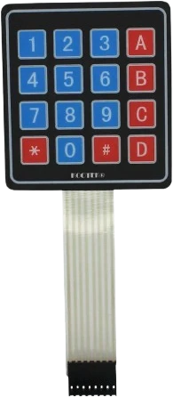
The 4x4 keypad is a grid of 16 momentary switches arranged as four rows and four columns. Each button simply connects one row line to one column line when pressed, so the whole keypad is passive: it needs no power, just eight digital pins on the microcontroller.
To read it, the microcontroller scans the matrix. It drives one row at a time and checks which column line responds, which tells it exactly which of the 16 keys is down. A keypad library (such as the Arduino Keypad library) handles this scanning and maps each intersection to a character like 0-9, A-D, star, or hash.
Reading 16 keys with only 8 pins is the whole point of the matrix layout. The trade-off is that reliable multi-key detection needs extra diodes, so a plain keypad is best for one keypress at a time.
| Pin | Function | Type |
|---|---|---|
R1 Row 1 | Digital | Bidirectional (GPIO) |
R2 Row 2 | Digital | Bidirectional (GPIO) |
R3 Row 3 | Digital | Bidirectional (GPIO) |
R4 Row 4 | Digital | Bidirectional (GPIO) |
C1 Col 1 | Digital | Bidirectional (GPIO) |
C2 Col 2 | Digital | Bidirectional (GPIO) |
C3 Col 3 | Digital | Bidirectional (GPIO) |
C4 Col 4 | Digital | Bidirectional (GPIO) |
Verified from the Tinkered component library.
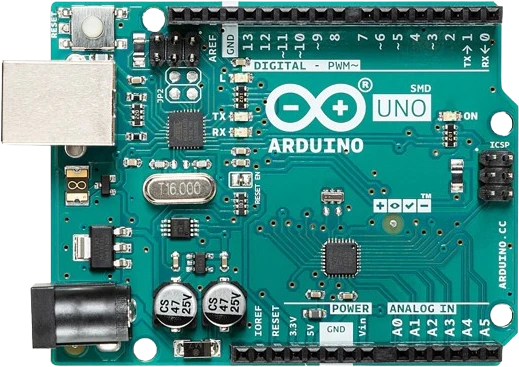
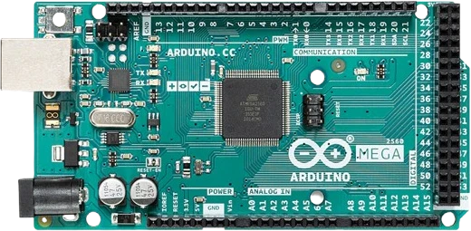
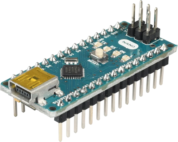
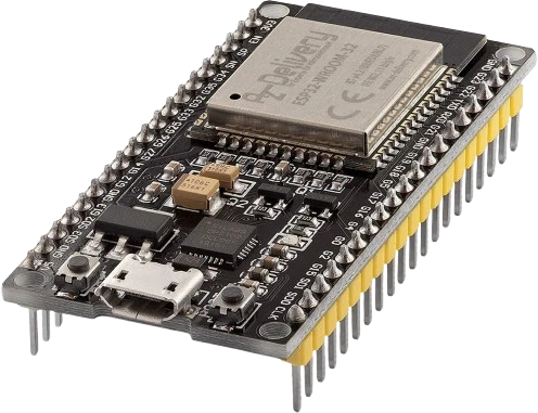
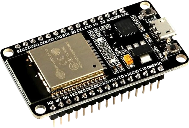
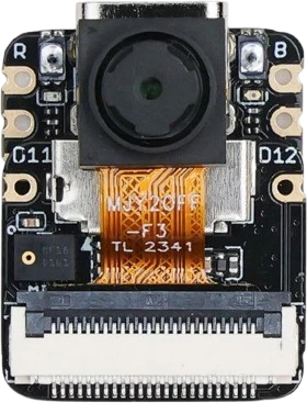
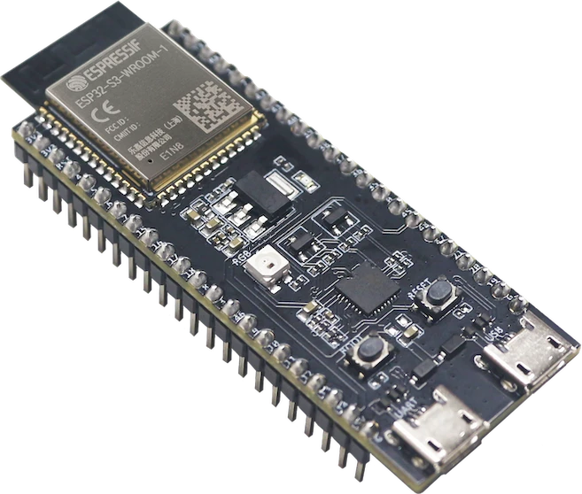
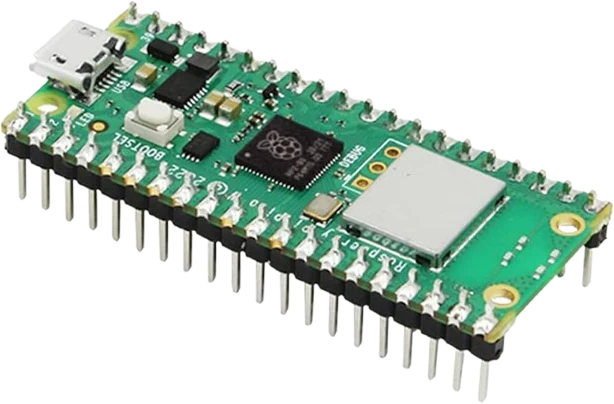
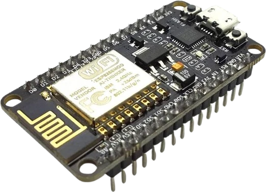
The 4×4 Keypad connects to any of the microcontrollers supported in Tinkered.
The eight pins must be listed in code in the same order as they are wired. A swapped row or column makes the keypad report the wrong characters even though every key works.
Without pull-up or pull-down resistors the input pins float and report random presses. Use the internal pull-ups the keypad library expects.
A plain matrix keypad without diodes suffers from ghosting, so pressing several keys at once can register phantom keys. Design for one key at a time or add per-switch diodes.
The keypad is just switches. Wiring a VCC to it does nothing useful and, if bridged to a scan line, can confuse the reading. Only the eight signal pins are needed.
Enter a PIN to release a servo or relay-driven latch, a classic access-control build.
Feed digits into a display or logger for a simple calculator or data-entry pad.
Use the letter keys to move through menus or switch modes on a project.
Build safe-cracking or memory games around entering the right key sequence.
Drop the 4×4 Keypad into a circuit, write firmware, and simulate it in your browser, then deploy to real hardware. All in one editable Tinkered project.