INA219 Current Sensor
A high-side current, voltage and power monitor over I2C: up to 26 V and ±3.2 A on the common 0.1 Ω module.
- Chip supply3 V to 5.5 V, 1 mA max (0.7 mA typical)
- Bus voltage sensed0 to 26 V (32 V or 16 V ADC range, 26 V maximum on the pins)
- Shunt voltage range±40, ±80, ±160 or ±320 mV (PGA /1 to /8)
- Resolution12-bit ADC; 10 µV shunt step, 4 mV bus step
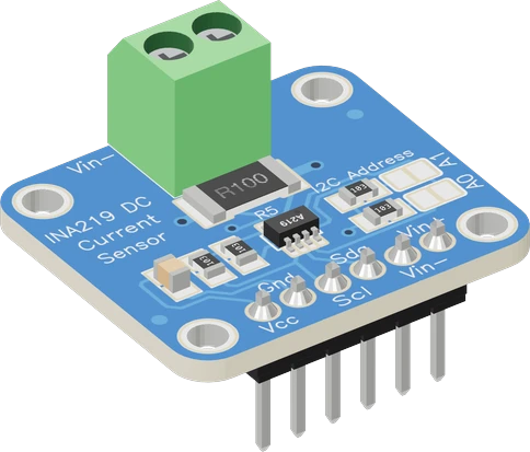
The INA219 is TI's I2C current, voltage and power monitor: it reads the drop across a shunt (up to ±320 mV) and the bus voltage (0 to 26 V) while running from a 3 V to 5.5 V supply (TI INA219 datasheet SBOS448G, pp. 1, 5, 6). The common module puts a 0.1 Ω shunt between VIN+ and VIN-, so it measures up to ±3.2 A at 0.8 mA resolution (Adafruit INA219 guide). Wire VCC and GND to your board, SDA and SCL to the I2C pins, and put VIN+ and VIN- in series with the load's positive supply; the default address is 0x40 (datasheet, p. 14).
The INA219 is a zero-drift current shunt and power monitor from Texas Instruments. It measures two things, the small voltage across a shunt resistor and the bus voltage on the load side, and with a calibration value it reports current in amperes and power in watts directly over I2C or SMBus (TI datasheet SBOS448G, p. 1). The chip runs from 3 V to 5.5 V, draws 1 mA at most, and senses a bus anywhere from 0 to 26 V whatever its own supply (pp. 1, 6), so a 3.3 V ESP32 can monitor a 12 V motor supply.
The blue breakout most makers buy follows Adafruit's design: a 0.1 Ω, 1 % shunt between VIN+ and VIN-, which with the chip's ±320 mV maximum shunt range gives ±3.2 A, at 0.8 mA resolution from the 12-bit ADC (Adafruit INA219 guide; TI datasheet, p. 5). The header carries VCC, GND, SCL, SDA, VIN- and VIN+, with 10 kΩ pull-ups on SDA and SCL, and a screw terminal duplicates VIN+ and VIN- for heavier wires. Two solder jumpers on A0 and A1 select one of four addresses, 0x40 to 0x45.
The INA219 is a high-side monitor: it sits in the positive supply line, between the source and the load, and reads the bus voltage at VIN- against ground (p. 9). Shunt voltage resolves to 10 µV and bus voltage to 4 mV per step (p. 5), with current and bus-voltage error of ±0.5 % maximum at 25 °C (p. 5). Programmable averaging, from one to 128 samples, trades speed for noise (p. 10).
INA219 Current Sensor pinout
| Pin | Function | Type |
|---|---|---|
| VCC | VCC: 3-5.5 V, the chip's supply (and the I2C pull-ups')3–5 V | power in |
| GND | GND (in common with the measured circuit's, for the bus voltage) | power in |
| SCL | I2C SCL | bidirectional |
| SDA | I2C SDA | bidirectional |
| VIN_N | ADC IN-: the shunt's load side, 0-26 V | passive |
| VIN_P | ADC IN+: the shunt's supply side, 0-26 V | passive |
| TERM_VIN_N | Terminal VIN-: to the load's + | passive |
| TERM_VIN_P | Terminal VIN+: from the supply's + | passive |
How to wire the INA219 Current Sensor
Pin by pin, for the board you have.
| INA219 Current Sensor | Arduino Uno | Note |
|---|---|---|
| VCC | 5V | |
| GND | GND | |
| SDA | SDA | |
| SCL | SCL | |
| VIN_P | 5V |
| INA219 Current Sensor | ESP32 DevKit V1 | Note |
|---|---|---|
| VCC | 3V3 | |
| GND | GND | |
| SDA | GPIO21 (D21) | |
| SCL | GPIO22 (D22) | |
| VIN_P | 3V3 |
| INA219 Current Sensor | Raspberry Pi Pico | Note |
|---|---|---|
| VCC | 3V3 | |
| GND | GND | |
| SDA | GP4 | |
| SCL | GP5 | |
| VIN_P | 3V3 |
INA219 Current Sensor code
Every example here compiles for its board.
// INA219 Current Sensor on Arduino Uno: wiring and a free simulation at https://www.tinkered.ai/components/ina219-current-sensor
#include <Arduino.h>
#include <Wire.h>
#include <Adafruit_INA219.h>

Adafruit_INA219 ina219;   // 0x40: the module's A0/A1 jumpers open

void setup() {
  Serial.begin(115200);
  if (!ina219.begin()) {
    Serial.println("INA219 not found: check VCC, SDA/SCL and its address jumpers");
    while (true) delay(10);
  }
  // begin() calibrates for 32 V / 2 A (0.1 mA steps); for loads under 400 mA:
  // ina219.setCalibration_16V_400mA();
}

void loop() {
  float shuntMv = ina219.getShuntVoltage_mV();
  float busV = ina219.getBusVoltage_V();     // VIN- against GND: the load's voltage
  float currentMa = ina219.getCurrent_mA();
  float powerMw = ina219.getPower_mW();
  float supplyV = busV + shuntMv / 1000.0;   // VIN+: the supply's voltage

  Serial.print("Load: ");
  Serial.print(busV, 3);
  Serial.print(" V  Supply: ");
  Serial.print(supplyV, 3);
  Serial.print(" V  Current: ");
  Serial.print(currentMa, 1);
  Serial.print(" mA  Power: ");
  Serial.print(powerMw, 0);
  Serial.println(" mW");
  delay(500);
}
// INA219 Current Sensor on ESP32 DevKit V1: wiring and a free simulation at https://www.tinkered.ai/components/ina219-current-sensor
#include <Arduino.h>
#include <Wire.h>
#include <Adafruit_INA219.h>

Adafruit_INA219 ina219;   // 0x40: the module's A0/A1 jumpers open

void setup() {
  Serial.begin(115200);
  if (!ina219.begin()) {
    Serial.println("INA219 not found: check VCC, SDA/SCL and its address jumpers");
    while (true) delay(10);
  }
  // begin() calibrates for 32 V / 2 A (0.1 mA steps); for loads under 400 mA:
  // ina219.setCalibration_16V_400mA();
}

void loop() {
  float shuntMv = ina219.getShuntVoltage_mV();
  float busV = ina219.getBusVoltage_V();     // VIN- against GND: the load's voltage
  float currentMa = ina219.getCurrent_mA();
  float powerMw = ina219.getPower_mW();
  float supplyV = busV + shuntMv / 1000.0;   // VIN+: the supply's voltage

  Serial.print("Load: ");
  Serial.print(busV, 3);
  Serial.print(" V  Supply: ");
  Serial.print(supplyV, 3);
  Serial.print(" V  Current: ");
  Serial.print(currentMa, 1);
  Serial.print(" mA  Power: ");
  Serial.print(powerMw, 0);
  Serial.println(" mW");
  delay(500);
}
// INA219 Current Sensor on Raspberry Pi Pico: wiring and a free simulation at https://www.tinkered.ai/components/ina219-current-sensor
#include <Arduino.h>
#include <Wire.h>
#include <Adafruit_INA219.h>

Adafruit_INA219 ina219;   // 0x40: the module's A0/A1 jumpers open

void setup() {
  Serial.begin(115200);
  if (!ina219.begin()) {
    Serial.println("INA219 not found: check VCC, SDA/SCL and its address jumpers");
    while (true) delay(10);
  }
  // begin() calibrates for 32 V / 2 A (0.1 mA steps); for loads under 400 mA:
  // ina219.setCalibration_16V_400mA();
}

void loop() {
  float shuntMv = ina219.getShuntVoltage_mV();
  float busV = ina219.getBusVoltage_V();     // VIN- against GND: the load's voltage
  float currentMa = ina219.getCurrent_mA();
  float powerMw = ina219.getPower_mW();
  float supplyV = busV + shuntMv / 1000.0;   // VIN+: the supply's voltage

  Serial.print("Load: ");
  Serial.print(busV, 3);
  Serial.print(" V  Supply: ");
  Serial.print(supplyV, 3);
  Serial.print(" V  Current: ");
  Serial.print(currentMa, 1);
  Serial.print(" mA  Power: ");
  Serial.print(powerMw, 0);
  Serial.println(" mW");
  delay(500);
}
Before you wire it
- VCC to the microcontroller board's logic supply (5V on an Uno, 3V3 on an ESP32, a Pico, an STM32), GND to its GND. Wire SDA/SCL to its I2C pins (Uno A4/A5, ESP32 GPIO21/22, Pico GP4/GP5, Nucleo D14/D15, NodeMCU D2/D1). No extra pull-ups: the module has 10 kΩ on both.
- The module goes in series on the supply's + (high side): the supply's + to VIN+, VIN- to the load's +, the load's - to GND. All the load's current goes through the shunt and nothing else.
- The measured supply's - goes to the module's GND (the microcontroller board's GND). The bus voltage is read against it; without a common ground it reads nothing useful.
- The line stays within 0-26 V on both VIN pins, and its current within ±3.2 A.
- In code: Adafruit_INA219 ina219; (0x40) or Adafruit_INA219 ina219(0x41);, then ina219.begin(), and check it returned true.
- Two modules: each its own address (jumpers and addr=), each its own Adafruit_INA219 object.
- Name your own constants without the library's names. Adafruit_INA219.h #defines INA219_ADDRESS, INA219_READ, every INA219_REG_* and INA219_CONFIG_*_MASK, and declares the enums INA219_CONFIG_GAIN_*, INA219_CONFIG_BADCRES_*, INA219_CONFIG_SADCRES_*, INA219_CONFIG_MODE_*. A constant named the same breaks the build in the library's header. Use names of your own: SENSOR_ADDR, READ_INTERVAL_MS.
- No VCC outside 3-5.5 V, and NO VCC at 5 V on a 3.3 V board: the pull-ups would put 5 V on SDA and SCL.
- No line above 26 V on VIN+ or VIN-: the chip is destroyed.
- No VIN+ and VIN- straight across a supply with no load between them: a short through 0.1 Ω.
- No module on the low side (VIN- on GND): the current reads, but the bus voltage and power read 0.
- No motor, LED strip or other load powered from the module's VCC: it is the chip's supply; the load's current goes through VIN+ and VIN-.
- VCC powers the chip only: 3 V to 5.5 V (TI datasheet, p. 6). Wire it to the microcontroller board's logic voltage, because the module's 10 kΩ pull-ups take SDA and SCL to VCC.
- Put the module in series on the positive side: the supply's + to VIN+, VIN- to the load's +, the load's - to ground. All the load current flows through the shunt.
- Share ground between the measured circuit and the module. The bus voltage is read at VIN- against the module's GND (p. 9); without a common ground the bus voltage and power read nothing useful.
- Keep VIN+ and VIN- between -0.3 V and 26 V (p. 4) and the current within ±3.2 A on the 0.1 Ω module (Adafruit guide). Use the screw terminal for currents above a few hundred milliamps.
- The A0 and A1 jumpers set the address: none 0x40, A0 0x41, A1 0x44, both 0x45 (p. 14). Up to four modules share one bus.
Specifications
- Chip supply
- 3 V to 5.5 V, 1 mA max (0.7 mA typical)TI INA219 datasheet SBOS448G, p. 6
- Bus voltage sensed
- 0 to 26 V (32 V or 16 V ADC range, 26 V maximum on the pins)TI INA219 datasheet SBOS448G, pp. 1, 4, 5
- Shunt voltage range
- ±40, ±80, ±160 or ±320 mV (PGA /1 to /8)TI INA219 datasheet SBOS448G, p. 5
- Resolution
- 12-bit ADC; 10 µV shunt step, 4 mV bus stepTI INA219 datasheet SBOS448G, p. 5
- Accuracy
- ±0.5 % max current and bus voltage error at 25 °CTI INA219 datasheet SBOS448G, p. 5
- Module shunt and range
- 0.1 Ω, 1 %; ±3.2 A at 0.8 mA resolutionAdafruit INA219 breakout guide
- I2C addresses
- 0x40, 0x41, 0x44, 0x45 with A0 and A1 (16 possible on the chip)TI INA219 datasheet SBOS448G, pp. 1, 14
- I2C clock
- Up to 400 kHz fast mode, 2.56 MHz high-speed modeTI INA219 datasheet SBOS448G, p. 6
- Conversion time
- 532 µs typical at 12 bitsTI INA219 datasheet SBOS448G, p. 5
- Operating temperature
- -40 °C to 125 °CTI INA219 datasheet SBOS448G, p. 1
- Supply voltage
- 3–5 V
- Maximum supply voltage
- 5.5 V
- Interface
- I2C
- I2C address
- 0x40
- On-board I2C pull-ups
- Yes (10 kΩ)
- Dimensions
- 25.4 × 22.5 × 18.6 mm
- Weight
- 3 g
From the Texas Instruments INA219 (Adafruit 904 layout, generic module)'s datasheet, published by Texas Instruments INA219 (Adafruit 904 layout, generic module).
Common mistakes
Wiring it on the low side
With VIN- on ground the current still reads, but the bus voltage the chip measures at VIN- is 0, so power reads 0 too. The INA219 is meant for the high side, in the positive supply line (TI datasheet, p. 9).
No common ground
The bus voltage is measured against the module's GND. If the measured supply's negative is not tied to the microcontroller's ground, voltage and power readings are meaningless.
VIN+ and VIN- across a supply with no load
The 0.1 Ω shunt is not a load. Connecting the two VIN pins straight across a power supply shorts it through the shunt. Always put the load between VIN- and ground.
Powering the load from the module's VCC
VCC is only the chip's supply. The load's current must pass through VIN+ and VIN-, or the INA219 never sees it.
Exceeding 26 V
The ADC can be set to a 32 V range, but TI warns that no more than 26 V may ever be applied to the chip (datasheet, p. 5). A 24 V system with spikes needs margin or protection.
INA219 Current Sensor questions
What is the INA219 I2C address?
0x40 with both address jumpers open. Bridging A0 gives 0x41, A1 gives 0x44, and both give 0x45 (TI datasheet, p. 14). The chip itself supports 16 addresses by tying A0 and A1 to GND, VS, SDA or SCL (p. 1), but the common module only exposes the four.
Can I use the INA219 with 3.3 V and 5 V boards?
Yes. The chip runs from 3 V to 5.5 V (TI datasheet, p. 6), so power VCC from the board's logic voltage: 3.3 V on an ESP32 or Pico, 5 V on an Uno. The measured bus can be 0 to 26 V regardless of VCC (p. 1).
INA219 vs ACS712: which current sensor should I use?
The INA219 reads current, bus voltage and power digitally over I2C with a 12-bit ADC and ±0.5 % maximum error, up to 26 V (TI datasheet, pp. 1, 5), and on the 0.1 Ω module up to ±3.2 A (Adafruit guide). The ACS712 is a Hall-effect sensor with an analog output, isolated from the measured line and rated ±5 A, ±20 A or ±30 A depending on version, on a 5 V supply (Allegro ACS712 datasheet Rev. 22, pp. 1, 2, 5). Choose the INA219 for precise low-current DC and power, the ACS712 for larger currents or when you need isolation.
Why does my INA219 read 0 V or wrong current?
Bus voltage at 0 usually means the module sits on the low side or lacks a common ground (TI datasheet, p. 9). Negative current means VIN+ and VIN- are swapped. Readings that stop rising mean the current passed the calibration's range: ±3.2 A on the 0.1 Ω module (Adafruit guide). If begin() fails, check VCC, the I2C pins and the address jumpers (p. 14).
What is the maximum current the INA219 module can measure?
±3.2 A with the module's 0.1 Ω shunt, set by the chip's ±320 mV maximum shunt range (TI datasheet, p. 5; Adafruit guide). For more current, replace the shunt with a smaller value and recalibrate, keeping the shunt's power rating in mind.
Can the INA219 measure AC current?
No. It is a DC monitor: the bus input must stay between -0.3 V and 26 V (TI datasheet, p. 4). It does measure current in both directions, reported as positive or negative (p. 1).
Build something with the INA219 Current Sensor
- Build this
USB or battery power meter
Show volts, milliamps and milliwatts on an OLED for any DC device.
- Build this
Solar panel monitor
Log a panel's voltage, current and energy through the day.
- Build this
Battery runtime tester
Measure the total charge a battery delivers into a load.
- Build this
Motor current watch
Detect a stalled or overloaded motor from its current draw.
This page as plain Markdown, for ChatGPT, Claude or your own agent. /components/ina219-current-sensor.md