INA219 Current Sensor with a Raspberry Pi Pico
A high-side current, voltage and power monitor over I2C: up to 26 V and ±3.2 A on the common 0.1 Ω module.
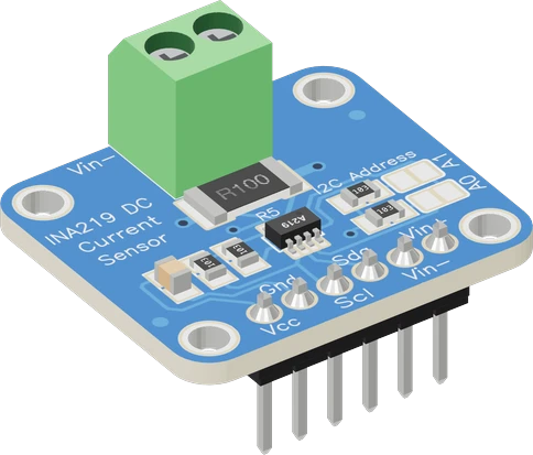
On this page the INA219 runs from the Raspberry Pi Pico's 3V3, talks on I2C0 (SDA GP4, SCL GP5) at 0x40, and has VIN+ on the Pico's 3V3 rail too. That makes it measure whatever load you hang on VIN-, fed by the Pico's own regulator, so the load counts against the 3V3 pin's budget.
Wiring the INA219 Current Sensor to the Raspberry Pi Pico
Pin by pin.
| INA219 Current Sensor | Raspberry Pi Pico |
|---|---|
| VCC | 3V3 |
| GND | GND |
| SDA | GP4 |
| SCL | GP5 |
| VIN_P | 3V3 |
What to know on the Raspberry Pi Pico
- A load on VIN- here draws from the Pico's 3V3 pin, which Raspberry Pi recommends keeping under 300 mA. For a bigger load, move VIN+ to its own supply: the INA219 senses 0 to 26 V on the bus whatever its own VCC.Raspberry Pi Pico datasheet, release 21, p. 8; TI INA219 datasheet SBOS448G, pp. 1, 4, 5
- The chip runs from 3 V to 5.5 V, so 3V3 suits it, and its 10 kOhm pull-ups then hold SDA and SCL at 3.3 V on GP4 and GP5.TI INA219 datasheet SBOS448G, p. 6
- The measured supply's ground must be the Pico's ground: the bus voltage is read against GND, and without a common ground it reads nothing useful.TI INA219 datasheet SBOS448G, bus voltage measured to GND
- begin() calibrates for 32 V and 2 A. A Pico 3V3 load stays far below 400 mA, so setCalibration_16V_400mA() gives finer steps.Adafruit INA219 library
INA219 Current Sensor code for the Raspberry Pi Pico
Compiled for rp2040:rp2040:rpipico on 2026-10-30.
// INA219 Current Sensor on Raspberry Pi Pico: wiring and a free simulation at https://www.tinkered.ai/components/ina219-current-sensor/raspberry-pi-pico
#include <Arduino.h>
#include <Wire.h>
#include <Adafruit_INA219.h>

Adafruit_INA219 ina219;   // 0x40: the module's A0/A1 jumpers open

void setup() {
  Serial.begin(115200);
  if (!ina219.begin()) {
    Serial.println("INA219 not found: check VCC, SDA/SCL and its address jumpers");
    while (true) delay(10);
  }
  // begin() calibrates for 32 V / 2 A (0.1 mA steps); for loads under 400 mA:
  // ina219.setCalibration_16V_400mA();
}

void loop() {
  float shuntMv = ina219.getShuntVoltage_mV();
  float busV = ina219.getBusVoltage_V();     // VIN- against GND: the load's voltage
  float currentMa = ina219.getCurrent_mA();
  float powerMw = ina219.getPower_mW();
  float supplyV = busV + shuntMv / 1000.0;   // VIN+: the supply's voltage

  Serial.print("Load: ");
  Serial.print(busV, 3);
  Serial.print(" V  Supply: ");
  Serial.print(supplyV, 3);
  Serial.print(" V  Current: ");
  Serial.print(currentMa, 1);
  Serial.print(" mA  Power: ");
  Serial.print(powerMw, 0);
  Serial.println(" mW");
  delay(500);
}
INA219 Current Sensor on the Raspberry Pi Pico: questions
Can the INA219 measure the Pico's own current?
Not as wired here: VIN+ on 3V3 measures loads fed from the Pico's 3V3 pin, not the Pico itself. To measure the whole board, put the shunt between the supply and VSYS, which accepts 1.8 V to 5.5 V (Pico datasheet, p. 8).
Can a Pico read an INA219 on a 12 V circuit?
Yes. Keep VCC on 3V3 and put VIN+ and VIN- in series with the 12 V line; the bus may be 0 to 26 V regardless of VCC (TI SBOS448G, p. 1). Join the grounds.
How many INA219 modules fit on the Pico's bus?
Four on the common module, at 0x40, 0x41, 0x44 and 0x45 set by A0 and A1 (TI SBOS448G, p. 14), each with its own object.
Keep going
This guide as plain Markdown. /components/ina219-current-sensor/raspberry-pi-pico.md