INA219 vs ACS712
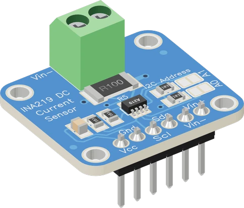
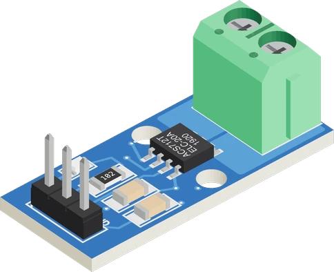
The INA219 is the precise DC choice: it reports current, bus voltage up to 26 V and power over I2C, resolving 0.8 mA on the common 0.1 Ω module with a ±3.2 A ceiling (TI INA219 datasheet SBOS448G, pp. 1, 5; Adafruit INA219 guide). The ACS712 is the high-current and AC choice: a Hall-effect sensor with an isolated 1.2 mΩ path, ±5 A, ±20 A or ±30 A, read as an analog voltage that moves 100 mV/A on the 20 A version (Allegro ACS712 datasheet Rev. 22, pp. 1, 2, 5). The ACS712 also needs 4.5 V to 5.5 V, where the INA219 runs from 3 V to 5.5 V (Allegro p. 5; TI p. 6).
Side by side
| INA219 | ACS712 | |
|---|---|---|
| Sensing methodTI INA219 datasheet SBOS448G, p. 5; Allegro ACS712 datasheet Rev. 22, pp. 1, 5 | Voltage across a shunt resistor (±40 to ±320 mV) | Hall effect on a 1.2 mΩ copper path |
| Current rangeAdafruit INA219 guide; TI INA219 datasheet SBOS448G, p. 5; Allegro ACS712 datasheet Rev. 22, p. 2 | ±3.2 A with the module's 0.1 Ω shunt | ±5 A, ±20 A or ±30 A by chip version |
| OutputTI INA219 datasheet SBOS448G, p. 1; Allegro ACS712 datasheet Rev. 22, pp. 2, 5 | Digital over I2C: current, bus voltage, power | Analog voltage, VCC/2 at 0 A; 185, 100 or 66 mV/A |
| ResolutionTI INA219 datasheet SBOS448G, p. 5; Adafruit INA219 guide; Allegro ACS712 datasheet Rev. 22, p. 2 | 12-bit ADC: about 0.8 mA steps across ±3.2 A on the 0.1 Ω module (10 µV register LSB) | Set by your ADC: about 49 mA per step on a 10-bit, 5 V reading of the 20 A version |
| AccuracyTI INA219 datasheet SBOS448G, p. 5; Allegro ACS712 datasheet Rev. 22, p. 6 | ±0.5 % max current error at 25 °C | ±1.5 % total output error at 25 °C |
| AC or DCTI INA219 datasheet SBOS448G, pp. 1, 4; Allegro ACS712 datasheet Rev. 22, p. 1 | DC only, either direction; bus -0.3 V to 26 V | AC or DC, 80 kHz bandwidth |
| IsolationTI INA219 datasheet SBOS448G, p. 9; Allegro ACS712 datasheet Rev. 22, pp. 1, 3 | None: shares ground with the measured circuit | 2.4 kVRMS minimum between the current path and the signal pins |
| SupplyTI INA219 datasheet SBOS448G, p. 6; Allegro ACS712 datasheet Rev. 22, p. 5 | 3 V to 5.5 V, 1 mA max | 4.5 V to 5.5 V, 10 mA typical |
| Bus voltage readingTI INA219 datasheet SBOS448G, pp. 1, 5 | 0 to 26 V, 4 mV step | None |
| Address or pinTI INA219 datasheet SBOS448G, p. 14; Allegro ACS712 datasheet Rev. 22, p. 1 | I2C 0x40, 0x41, 0x44 or 0x45 by jumper | One analog input per sensor |
Which one to pick
- Battery and solar logging, where voltage, current and power all matter: one I2C read gives all three (TI INA219 datasheet, p. 1).
- Milliamp-level loads such as a sleeping ESP32 or a sensor node: 0.8 mA steps on the 0.1 Ω module (Adafruit INA219 guide).
- 3.3 V boards with no analog headroom: it runs from 3 V and needs no divider (TI p. 6); up to four share one bus (p. 14).
- Motors, heaters and LED strips past 3.2 A, up to ±30 A on the 30A chip (Allegro ACS712 datasheet, p. 2).
- AC loads, read as RMS from samples, thanks to the 80 kHz bandwidth (p. 1).
- Circuits that must stay electrically isolated from the microcontroller: 2.4 kVRMS between the current path and the signal pins (pp. 1, 3).
Swapping one for the other
What changes in the wiring and the code.
- Wiring moves from an analog pin to I2C: the INA219 module's SDA and SCL go to the board's I2C pins and its VCC to the board's logic voltage, 3 V to 5.5 V (TI datasheet, p. 6). The ACS712 needs 5 V on VCC and one analog input (Allegro datasheet, p. 5).
- Both go in series with the load on the positive side: supply + to VIN+ (INA219) or IP+ (ACS712), then out to the load. The INA219 also needs a common ground to read bus voltage (TI p. 9); the ACS712 does not.
- Code changes from math to a library: amps = (volts - VCC/2) / sensitivity for the ACS712 (Allegro p. 5), getCurrent_mA() and getBusVoltage_V() from Adafruit_INA219 at address 0x40 by default (TI p. 14).
- Drop the divider: an ACS712 on a 3.3 V board needs OUT divided down, an INA219 talks I2C at the board's own level.
- Respect the new limit: the 0.1 Ω INA219 module stops at ±3.2 A and 26 V (Adafruit guide; TI p. 5), far below the ACS712's 20 A or 30 A.
INA219 or ACS712: questions
Which is more accurate for small currents?
The INA219. Its 12-bit ADC splits the 0.1 Ω module's ±3.2 A range into steps of about 0.8 mA (TI INA219 datasheet, p. 5; Adafruit guide). The ACS712's 20 A version moves 100 mV per amp and shows 11 mV peak-to-peak noise (Allegro datasheet, pp. 2, 6), about a tenth of an amp.
Can the INA219 measure AC?
No. Its bus inputs must stay between -0.3 V and 26 V, so it is a DC monitor, though it reads current in both directions (TI datasheet, pp. 1, 4). The ACS712 senses AC or DC up to 80 kHz (Allegro datasheet, p. 1).
Which works on a 3.3 V ESP32 or Pico?
The INA219 directly: it runs from 3 V to 5.5 V and talks I2C (TI datasheet, p. 6). The ACS712 must be powered from 5 V (4.5 V to 5.5 V, Allegro datasheet, p. 5) and its output divided down, for example 10 kΩ and 20 kΩ, before a 3.3 V ADC.
How much current can each handle?
The INA219 module reads ±3.2 A with its 0.1 Ω shunt (Adafruit guide), set by the chip's ±320 mV shunt range (TI datasheet, p. 5). The ACS712 reads ±5 A, ±20 A or ±30 A depending on the chip (Allegro datasheet, p. 2); the module's screw terminal and traces may limit continuous current further.
Does the ACS712 measure voltage or power?
No, current only. The INA219 also reads the bus voltage, 0 to 26 V in 4 mV steps, and computes power (TI datasheet, pp. 1, 5).
The two references
Checked on 2026-10-29 against 3 sources, the makers’ datasheets first.
This comparison as plain Markdown. /compare/ina219-current-sensor-vs-acs712-current-sensor.md