ACS712 Current Sensor (20A)
A Hall-effect current sensor module that turns up to ±20 A, AC or DC, into an analog voltage centred on VCC/2.
- Supply voltage4.5 V to 5.5 V (5.0 V typical)
- Supply current10 mA typical, 13 mA max
- Sensitivity (20 A chip)100 mV/A typical (96 to 104 mV/A), ±20 A
- Other ranges05B: ±5 A at 185 mV/A; 30A: ±30 A at 66 mV/A
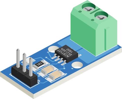
The ACS712 is a Hall-effect current sensor that outputs VCC/2 at zero current and moves 100 mV per amp on the ±20 A version, 185 mV/A on the ±5 A and 66 mV/A on the ±30 A (Allegro ACS712 datasheet Rev. 22, pp. 2, 5). Power the module from 5 V (4.5 V to 5.5 V, p. 5), put the measured line in series through its IP+ and IP- terminal, and read OUT on an analog pin: amps = (volts - VCC/2) / 0.100. On a 3.3 V board, scale OUT down with a resistor divider first.
The ACS712 measures current through a 1.2 mΩ copper path inside its package. The current's magnetic field is read by a Hall sensor on the same die and turned into a proportional voltage, with the measured path electrically isolated from the signal pins at 2.4 kVRMS minimum (Allegro datasheet, p. 1). That lets it sense the supply of a 12 V motor or another circuit without sharing its ground.
With no current the output sits at VCC × 0.5, 2.5 V on a 5 V supply, and rises for current flowing from IP+ to IP- and falls for current the other way (pp. 1, 5). It senses AC or DC. Both the zero point and the sensitivity are ratiometric, scaling with the supply (p. 10), which suits an Arduino whose ADC reference is the same 5 V. Bandwidth is 80 kHz and the output rises in 5 µs after a current step (p. 1).
The common blue module puts the chip on a board with a screw terminal for the measured line and a three-pin VCC, OUT, GND header. Three chips share the module: the ACS712ELCTR-05B at ±5 A and 185 mV/A, the -20A at ±20 A and 100 mV/A, and the -30A at ±30 A and 66 mV/A (p. 2). Total output error is ±1.5 % at 25 °C (p. 6), though a 10-bit ADC limits resolution more: one 4.9 mV step is about 49 mA on the 20 A version.
ACS712 Current Sensor (20A) pinout
| Pin | Function | Type |
|---|---|---|
| VCC | VCC: 5 V (4.5-5.5 V)4.5–5 V | power in |
| OUT | ADC VIOUT: 2.5 V at 0 A, 100 mV/A | output |
| GND | GND | power in |
| IP_P | ADC IP+: the current path, 1.2 mΩ, isolated 2.1 kV from the signal side | passive |
| IP_N | ADC IP-: the current path's other end | passive |
How to wire the ACS712 Current Sensor (20A)
Pin by pin, for the board you have.
| ACS712 Current Sensor (20A) | Arduino Uno | Note |
|---|---|---|
| VCC | 5V | |
| GND | GND | |
| OUT | A0 |
| ACS712 Current Sensor (20A) | ESP32 DevKit V1 | Note |
|---|---|---|
| VCC | VIN | |
| GND | GND | |
| OUT | GPIO33 (D33) | through a 10 kΩ resistor, with a 20 kΩ resistor from the board pin to GND: a divider that scales OUT by 2/3, so its 5 V swing stays under 3.3 V |
- VCC is on VIN, which gives about 5 V only while the board is powered from USB.
| ACS712 Current Sensor (20A) | Raspberry Pi Pico | Note |
|---|---|---|
| VCC | VBUS | |
| GND | GND | |
| OUT | GP28 | through a 10 kΩ resistor, with a 20 kΩ resistor from the board pin to GND: a divider that scales OUT by 2/3, so its 5 V swing stays under 3.3 V |
- VCC is on VBUS, which gives about 5 V only while the board is powered from USB.
ACS712 Current Sensor (20A) code
Every example here compiles for its board.
// ACS712 Current Sensor (20A) on Arduino Uno: wiring and a free simulation at https://www.tinkered.ai/components/acs712-current-sensor
#include <Arduino.h>

const int SENSE_PIN = A0;
const float SENS_V_PER_A = 0.100;   // 20 A module (0.185 for 5 A, 0.066 for 30 A)
const float VREF = 5.0;             // the Uno's ADC reference: its 5 V
const float ADC_MAX = 1024.0;       // 10 bits
const float ZERO_V = VREF / 2.0;    // OUT with no current: VCC / 2
const int SAMPLES = 64;

float readAmps() {
  long sum = 0;
  for (int i = 0; i < SAMPLES; i++) sum += analogRead(SENSE_PIN);
  float volts = (sum / (float)SAMPLES) * VREF / ADC_MAX;
  return (volts - ZERO_V) / SENS_V_PER_A;
}

void setup() {
  Serial.begin(115200);
  Serial.println("ACS712 ready");
}

void loop() {
  float amps = readAmps();
  Serial.print("Current: ");
  Serial.print(amps, 3);
  Serial.print(" A  (");
  Serial.print(amps * 1000.0, 0);
  Serial.println(" mA)");
  delay(500);
}
// ACS712 Current Sensor (20A) on ESP32 DevKit V1: wiring and a free simulation at https://www.tinkered.ai/components/acs712-current-sensor
#include <Arduino.h>

// ACS712 on an ESP32 DevKit: OUT reaches GPIO33 through a 10 kΩ / 20 kΩ divider,
// so the pin sees 2/3 of OUT (the 2.5 V zero becomes about 1.67 V).
const int SENSE_PIN = 33;
const float SENS_V_PER_A = 0.100;   // 20 A module (0.185 for 5 A, 0.066 for 30 A)
const float DIVIDER = 1.5;          // (10 kΩ + 20 kΩ) / 20 kΩ: OUT = pin voltage x 1.5
const int SAMPLES = 64;
float zeroV = 2.5;                  // OUT with no current (VCC / 2), measured in setup()

// OUT in volts: analogReadMilliVolts() applies the chip's own ADC calibration,
// which a plain analogRead() * 3.3 / 4095 does not (the ESP32's ADC is not linear)
float readOutVolts() {
  uint32_t mv = 0;
  for (int i = 0; i < SAMPLES; i++) mv += analogReadMilliVolts(SENSE_PIN);
  return (mv / (float)SAMPLES) / 1000.0 * DIVIDER;
}

void setup() {
  Serial.begin(115200);
  analogSetPinAttenuation(SENSE_PIN, ADC_11db);   // 11 dB, the widest range: Espressif rates it accurate to about 2.45 V
  delay(100);
  zeroV = readOutVolts();                          // start with no current flowing
  Serial.print("ACS712 ready, zero at ");
  Serial.print(zeroV, 3);
  Serial.println(" V");
}

void loop() {
  float amps = (readOutVolts() - zeroV) / SENS_V_PER_A;
  Serial.print("Current: ");
  Serial.print(amps, 3);
  Serial.print(" A  (");
  Serial.print(amps * 1000.0, 0);
  Serial.println(" mA)");
  delay(500);
}
// ACS712 Current Sensor (20A) on Raspberry Pi Pico: wiring and a free simulation at https://www.tinkered.ai/components/acs712-current-sensor
#include <Arduino.h>

// ACS712 on a Raspberry Pi Pico: OUT reaches GP28 through a 10 kΩ / 20 kΩ divider,
// so the pin sees 2/3 of OUT (the 2.5 V zero becomes about 1.67 V).
const int SENSE_PIN = 28;           // GP28 (ADC2)
const float SENS_V_PER_A = 0.100;   // 20 A module (0.185 for 5 A, 0.066 for 30 A)
const float ADC_VREF = 3.3;         // the Pico's ADC reference: its 3.3 V rail
const float ADC_STEPS = 4096.0;     // 12 bits, set in setup() (arduino-pico defaults to 10)
const float DIVIDER = 1.5;          // (10 kΩ + 20 kΩ) / 20 kΩ: OUT = pin voltage x 1.5
const int SAMPLES = 64;
float zeroV = 2.5;                  // OUT with no current (VCC / 2), measured in setup()

float readOutVolts() {
  uint32_t sum = 0;
  for (int i = 0; i < SAMPLES; i++) sum += analogRead(SENSE_PIN);
  return (sum / (float)SAMPLES) * ADC_VREF / ADC_STEPS * DIVIDER;
}

void setup() {
  Serial.begin(115200);
  analogReadResolution(12);
  delay(100);
  zeroV = readOutVolts();           // start with no current flowing
  Serial.print("ACS712 ready, zero at ");
  Serial.print(zeroV, 3);
  Serial.println(" V");
}

void loop() {
  float amps = (readOutVolts() - zeroV) / SENS_V_PER_A;
  Serial.print("Current: ");
  Serial.print(amps, 3);
  Serial.print(" A  (");
  Serial.print(amps * 1000.0, 0);
  Serial.println(" mA)");
  delay(500);
}
Before you wire it
- VCC to the board's 5V (VIN or 5V on an ESP32 DevKit or a Pico's VBUS, never 3V3), GND to its GND.
- OUT to an analog input: A0 on an Arduino, GP26-GP28 on a Pico, an ADC1 pin (GPIO32-GPIO39, e.g. GPIO34) on an ESP32.
- The measured line in series through the terminal: the supply's + to IP_P, IP_N to the load's +, the load's - to the supply's -.
- Set the range in the wiring when the module is not the 20 A one: acs_1 acs712-current-sensor range=5A, and use its sensitivity in the code.
- Convert in code: volts = raw * VREF / ADC_MAX, then amps = (volts - ZERO_V) / SENS.
- On an Uno, ZERO_V = 2.5 and SENS = 0.100 (20 A), 0.185 (5 A) or 0.066 (30 A).
- On an Uno the ADC's reference is the same 5 V as VCC, so no current reads 512 whatever the exact 5 V: amps = (raw - 512) * (5.0 / 1024) / SENS.
- Average several readings (16-100) for a steady value: a real ACS712 has about 10-20 mV of noise.
- A zero calibration (read OUT with no current at startup and use it as ZERO_V) is only valid with the load off at that moment.
- On an ESP32, read OUT with analogReadMilliVolts(), which applies the chip's own ADC calibration, then scale by the divider
- No VCC on 3V3: the ACS712 is specified from 4.5 V; its zero and sensitivity shrink and drift.
- No OUT straight into a 3.3 V board's ADC pin (ESP32, Pico, STM32): above a few amps OUT passes 3.3 V. Use the 10 kΩ / 20 kΩ divider.
- No IP+ and IP- straight across a supply with no load between them: a short through 1.2 mΩ.
- No measured current through VCC/GND: the load's current goes through the terminal only.
- Power VCC from 5 V: the ACS712 is specified from 4.5 V to 5.5 V (Allegro datasheet, p. 5). On an ESP32 or Pico use the board's 5 V, VIN or VBUS pin, never 3V3.
- Wire the measured current in series through the terminal: the supply's + to IP+, IP- to the load's +. Current flowing from IP+ to IP- raises the output above VCC/2 (p. 1).
- On a 3.3 V board, scale OUT before the ADC: OUT through 10 kΩ to the analog pin and 20 kΩ from that pin to GND gives two thirds of the voltage. Multiply the reading back by 1.5 in code.
- Convert with amps = (volts - VCC/2) / sensitivity, using 0.100 V/A for the 20 A module, 0.185 for the 5 A and 0.066 for the 30 A (p. 2). On an Uno, whose ADC reference is the same 5 V, zero current reads 512 counts.
- Average many samples. The 20 A chip shows 11 mV peak-to-peak noise even with a 47 nF filter capacitor and 2 kHz bandwidth (p. 6), about a tenth of an amp.
- OUT needs a load of 4.7 kΩ or more and no more than 10 nF (p. 5), so an ADC input or a divider is fine.
Specifications
- Supply voltage
- 4.5 V to 5.5 V (5.0 V typical)Allegro ACS712 datasheet Rev. 22, p. 5
- Supply current
- 10 mA typical, 13 mA maxAllegro ACS712 datasheet Rev. 22, p. 5
- Sensitivity (20 A chip)
- 100 mV/A typical (96 to 104 mV/A), ±20 AAllegro ACS712 datasheet Rev. 22, pp. 2, 6
- Other ranges
- 05B: ±5 A at 185 mV/A; 30A: ±30 A at 66 mV/AAllegro ACS712 datasheet Rev. 22, p. 2
- Zero-current output
- VCC × 0.5, ratiometricAllegro ACS712 datasheet Rev. 22, pp. 5, 10
- Total output error
- ±1.5 % at 25 °CAllegro ACS712 datasheet Rev. 22, p. 6
- Bandwidth and rise time
- 80 kHz; 5 µs output rise timeAllegro ACS712 datasheet Rev. 22, p. 1
- Primary conductor resistance
- 1.2 mΩAllegro ACS712 datasheet Rev. 22, p. 5
- Isolation
- 2.4 kVRMS minimum, pins 1-4 to pins 5-8Allegro ACS712 datasheet Rev. 22, pp. 1, 3
- Output load
- 4.7 kΩ min, 10 nF maxAllegro ACS712 datasheet Rev. 22, p. 5
- Maximum supply voltage
- 5.5 V
- Dimensions
- 31.2 × 13.3 × 13.6 mm
- Weight
- 5 g
From the Allegro ACS712ELCTR-20A (generic module)'s datasheet, published by Allegro ACS712ELCTR-20A (generic module).
Common mistakes
Powering it from 3.3 V
The ACS712 is specified from 4.5 V (Allegro datasheet, p. 5). Below that its zero point and sensitivity shift, so every reading is off. Use 5 V and divide OUT for a 3.3 V ADC.
OUT straight into a 3.3 V ADC
OUT swings above and below 2.5 V on a 5 V supply, so a few amps of current already pushes it past 3.3 V. Use a 10 kΩ / 20 kΩ divider on ESP32, Pico and STM32 boards.
Assuming exactly 2.5 V at zero
The zero point is VCC × 0.5 and follows the real supply (p. 5); USB 5 V is often a little low. Calibrate the zero at start-up with the load off, or on an Uno use raw - 512, which cancels the supply error.
Using the wrong sensitivity
The 5 A, 20 A and 30 A modules look identical but read 185, 100 and 66 mV/A (p. 2). Check the chip's suffix and use its figure, or every current is scaled wrong.
Shorting a supply across the terminal
IP+ to IP- is a 1.2 mΩ path (p. 5). Connected straight across a supply with no load in series, it is a dead short. The sensor always goes in series with the load.
ACS712 Current Sensor (20A) questions
Can I use the ACS712 with an ESP32 or Raspberry Pi Pico?
Yes, with two changes. Power the module from the board's 5 V pin, since the chip is specified from 4.5 V to 5.5 V (Allegro datasheet, p. 5), and pass OUT through a 10 kΩ / 20 kΩ divider so the ADC never sees more than 3.3 V. Then convert with the 3.3 V reference and multiply by 1.5 to undo the divider.
How do I calculate current from the ACS712 output?
amps = (VOUT - VCC/2) / sensitivity. VOUT is VCC × 0.5 at zero current (Allegro datasheet, p. 5), and the sensitivity is 0.185 V/A for the 05B, 0.100 V/A for the 20A and 0.066 V/A for the 30A chip (p. 2). A positive result means current flows from IP+ to IP-.
Why does my ACS712 read current when nothing is connected?
The zero point is half the actual supply, not exactly 2.5 V (p. 5), so a 4.9 V USB supply shifts it. The output also carries noise, 11 mV peak-to-peak on the 20 A chip (p. 6). Measure the zero with the load off at start-up and average 50 to 100 samples per reading.
Can the ACS712 measure AC current?
Yes. It senses AC or DC in either direction, with an 80 kHz bandwidth (Allegro datasheet, p. 1). For mains-frequency AC, sample over a few cycles, subtract the zero point and compute the RMS. Mains wiring belongs in an enclosure with a fuse, wired by someone qualified.
ACS712 vs INA219: which current sensor should I use?
The ACS712 measures up to ±30 A, AC or DC, through a 1.2 mΩ isolated path and outputs an analog voltage (Allegro datasheet, pp. 1, 2). The INA219 reads the drop across an external shunt, ±320 mV full scale, and reports current, bus voltage up to 26 V and power over I2C, with 0.5 % max error on the B grade (TI INA219 datasheet, pp. 1, 5). Use the ACS712 for high or AC currents and isolation, the INA219 for milliamp-level DC and power logging.
How much current can the ACS712 handle?
Its optimised range is ±5 A, ±20 A or ±30 A depending on the chip (Allegro datasheet, p. 2), and it survives a single 100 A pulse of 100 ms (p. 2). On a module, the screw terminal and PCB traces can limit continuous current further.
Build something with the ACS712 Current Sensor (20A)
- Build this
DC power meter
Measure a load's current and multiply by a measured supply voltage to log watts.
- Build this
Motor stall detector
Watch a DC motor's current and cut power when it spikes at a stall.
- Build this
Solar and battery monitor
Track charge and discharge current in both directions from one sensor.
- Build this
Appliance energy monitor
Sample AC current, compute RMS and estimate energy use over time.
- Build this
Overcurrent cutoff
Switch off a relay or MOSFET when the current passes a set limit.
This page as plain Markdown, for ChatGPT, Claude or your own agent. /components/acs712-current-sensor.md