ACS712 Current Sensor (20A) with a Raspberry Pi Pico
A Hall-effect current sensor module that turns up to ±20 A, AC or DC, into an analog voltage centred on VCC/2.
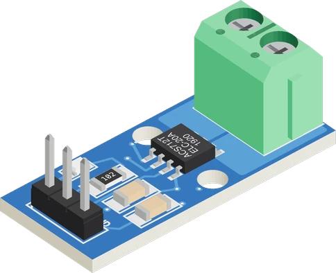
The ACS712 needs 4.5 to 5.5 V, so on the Raspberry Pi Pico its VCC goes to VBUS, the 5 V that arrives over USB. OUT idles near 2.5 V and can climb toward 5 V, so it reaches GP28 (ADC2) through a 10 kΩ / 20 kΩ divider that scales it to two thirds, and the sketch reads it at 12 bits against the Pico's 3.3 V rail.
Wiring the ACS712 Current Sensor (20A) to the Raspberry Pi Pico
Pin by pin.
| ACS712 Current Sensor (20A) | Raspberry Pi Pico | Note |
|---|---|---|
| VCC | VBUS | |
| GND | GND | |
| OUT | GP28 | through a 10 kΩ resistor, with a 20 kΩ resistor from the board pin to GND: a divider that scales OUT by 2/3, so its 5 V swing stays under 3.3 V |
- VCC is on VBUS, which gives about 5 V only while the board is powered from USB.
What to know on the Raspberry Pi Pico
- The RP2040's ADC has no reference of its own and measures against its supply, which on the Pico is the 3.3 V rail through an RC filter. That is why the sketch converts with ADC_VREF = 3.3 and 4096 steps, after analogReadResolution(12) lifts arduino-pico's default of 10 bits.Raspberry Pi Pico datasheet, release 21, section 4.3, p. 19; arduino-pico cores/rp2040/wiring_analog.cpp
- Raspberry Pi estimates an offset of about 30 mV on the Pico's ADC, from the converter's own current flowing through the 201 Ω filter resistor. The zero the sketch measures in setup() with no current flowing removes it together with the sensor's own zero offset.Raspberry Pi Pico datasheet, release 21, section 4.3, p. 19
- One 12 bit step is 0.81 mV at GP28, about 1.2 mV at OUT after the x1.5 divider, or 12 mA on the 20 A module. The RP2040's ADC is rated at 8.7 effective bits, so the 64 sample average in readOutVolts() matters more than the step size.RP2040 datasheet, section 5.5.3.4, Table 627
- The divider loads OUT with 30 kΩ, well above the 4.7 kΩ minimum Allegro allows. Seen from GP28 it is a 6.7 kΩ source, and the RP2040 rates its ADC input at 100 kΩ minimum, so at worst readings can sit several percent low; calibrate SENS_V_PER_A against a known current if that matters.Allegro ACS712 datasheet Rev. 22, p. 5; RP2040 datasheet, section 5.5.3.4, Table 627
ACS712 Current Sensor (20A) code for the Raspberry Pi Pico
Compiled for rp2040:rp2040:rpipico on 2026-10-30.
// ACS712 Current Sensor (20A) on Raspberry Pi Pico: wiring and a free simulation at https://www.tinkered.ai/components/acs712-current-sensor/raspberry-pi-pico
#include <Arduino.h>

// ACS712 on a Raspberry Pi Pico: OUT reaches GP28 through a 10 kΩ / 20 kΩ divider,
// so the pin sees 2/3 of OUT (the 2.5 V zero becomes about 1.67 V).
const int SENSE_PIN = 28;           // GP28 (ADC2)
const float SENS_V_PER_A = 0.100;   // 20 A module (0.185 for 5 A, 0.066 for 30 A)
const float ADC_VREF = 3.3;         // the Pico's ADC reference: its 3.3 V rail
const float ADC_STEPS = 4096.0;     // 12 bits, set in setup() (arduino-pico defaults to 10)
const float DIVIDER = 1.5;          // (10 kΩ + 20 kΩ) / 20 kΩ: OUT = pin voltage x 1.5
const int SAMPLES = 64;
float zeroV = 2.5;                  // OUT with no current (VCC / 2), measured in setup()

float readOutVolts() {
  uint32_t sum = 0;
  for (int i = 0; i < SAMPLES; i++) sum += analogRead(SENSE_PIN);
  return (sum / (float)SAMPLES) * ADC_VREF / ADC_STEPS * DIVIDER;
}

void setup() {
  Serial.begin(115200);
  analogReadResolution(12);
  delay(100);
  zeroV = readOutVolts();           // start with no current flowing
  Serial.print("ACS712 ready, zero at ");
  Serial.print(zeroV, 3);
  Serial.println(" V");
}

void loop() {
  float amps = (readOutVolts() - zeroV) / SENS_V_PER_A;
  Serial.print("Current: ");
  Serial.print(amps, 3);
  Serial.print(" A  (");
  Serial.print(amps * 1000.0, 0);
  Serial.println(" mA)");
  delay(500);
}
ACS712 Current Sensor (20A) on the Raspberry Pi Pico: questions
Can the ACS712 run from the Pico's 3V3 pin?
No. Allegro specifies 4.5 to 5.5 V (p. 5). VBUS only carries about 5 V while USB powers the Pico (Pico datasheet, p. 8), so on battery feed VCC from a separate 5 V supply and join its GND to the Pico's.
Which Pico pins can read the ACS712?
GP26, GP27 and GP28, the three ADC inputs on the header. The RP2040's fourth ADC channel is wired on the board to measure VSYS/3 (Pico datasheet, p. 7), and every ADC input must stay between 0 V and the ADC supply, which the divider ensures.
Why does the Pico print a negative current?
Current flowing from IP+ to IP- raises OUT above its zero (Allegro, p. 1); current the other way lowers it and the sketch prints a negative value. Swap the two wires on the screw terminal if your load's current should read positive.
Keep going
This guide as plain Markdown. /components/acs712-current-sensor/raspberry-pi-pico.md