INA219 Current Sensor with an ESP32 DevKit V1
A high-side current, voltage and power monitor over I2C: up to 26 V and ±3.2 A on the common 0.1 Ω module.
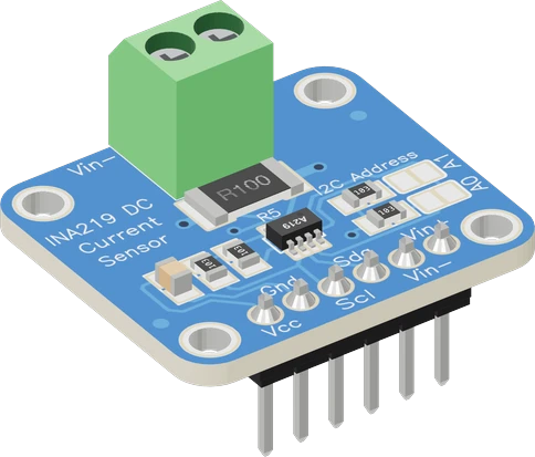
The INA219 module's VCC takes the ESP32 DevKit V1's 3V3 and its I2C goes to GPIO21 (SDA) and GPIO22 (SCL). The chip's supply and the line it measures are separate: VCC stays on 3V3 while VIN+ and VIN- can carry any line from 0 to 26 V, so a 3.3 V ESP32 can monitor a 12 V battery.
Wiring the INA219 Current Sensor to the ESP32 DevKit V1
Pin by pin.
| INA219 Current Sensor | ESP32 DevKit V1 |
|---|---|
| VCC | 3V3 |
| GND | GND |
| SDA | GPIO21 (D21) |
| SCL | GPIO22 (D22) |
| VIN_P | 3V3 |
What to know on the ESP32 DevKit V1
- Keep VCC on 3V3. The module's 10 kOhm pull-ups go to VCC, so VCC at 5 V would put 5 V on GPIO21 and GPIO22, above the ESP32's VDD + 0.3 V limit.Espressif ESP32 Series Datasheet v5.3, p. 52
- On the page VIN+ is on 3V3, so the module measures whatever load you hang on VIN-, fed from the ESP32's own 3.3 V rail. For a real project, put VIN+ and VIN- in series with the line you want to watch and keep its - on the ESP32's GND.TI INA219 datasheet SBOS448G, pp. 1, 4
- The INA219 replaces the ESP32's ADC for current and voltage: it reports ±0.5 % at 25 °C over I2C, unaffected by Wi-Fi, where the ESP32's ADC2 pins stop while Wi-Fi runs.TI INA219 datasheet SBOS448G, p. 5; ESP-IDF Programming Guide, ADC Oneshot Mode Driver
INA219 Current Sensor code for the ESP32 DevKit V1
Compiled for esp32:esp32:esp32 on 2026-10-30.
// INA219 Current Sensor on ESP32 DevKit V1: wiring and a free simulation at https://www.tinkered.ai/components/ina219-current-sensor/esp32
#include <Arduino.h>
#include <Wire.h>
#include <Adafruit_INA219.h>

Adafruit_INA219 ina219;   // 0x40: the module's A0/A1 jumpers open

void setup() {
  Serial.begin(115200);
  if (!ina219.begin()) {
    Serial.println("INA219 not found: check VCC, SDA/SCL and its address jumpers");
    while (true) delay(10);
  }
  // begin() calibrates for 32 V / 2 A (0.1 mA steps); for loads under 400 mA:
  // ina219.setCalibration_16V_400mA();
}

void loop() {
  float shuntMv = ina219.getShuntVoltage_mV();
  float busV = ina219.getBusVoltage_V();     // VIN- against GND: the load's voltage
  float currentMa = ina219.getCurrent_mA();
  float powerMw = ina219.getPower_mW();
  float supplyV = busV + shuntMv / 1000.0;   // VIN+: the supply's voltage

  Serial.print("Load: ");
  Serial.print(busV, 3);
  Serial.print(" V  Supply: ");
  Serial.print(supplyV, 3);
  Serial.print(" V  Current: ");
  Serial.print(currentMa, 1);
  Serial.print(" mA  Power: ");
  Serial.print(powerMw, 0);
  Serial.println(" mW");
  delay(500);
}
INA219 Current Sensor on the ESP32 DevKit V1: questions
Can an ESP32 measure a 12 V supply with the INA219?
Yes. The bus pins take 0 to 26 V whatever the chip's own 3 V to 5.5 V supply (TI datasheet, pp. 4, 6). Power VCC from 3V3 and wire the 12 V line through VIN+ and VIN-.
How many INA219 modules can one ESP32 read?
Four on a stock module, at 0x40, 0x41, 0x44 and 0x45 with the A0 and A1 jumpers (TI datasheet, p. 14), each with its own Adafruit_INA219 object.
Keep going
This guide as plain Markdown. /components/ina219-current-sensor/esp32.md