Freenove ESP32-WROVER Board
Freenove's ESP32 development board built on Espressif's ESP32-WROVER-E module (4 MB flash, 8 MB PSRAM), with a camera connector, a microSD slot, a CH340 USB bridge and two 20-pin headers.
- Module and coresESP32-WROVER-E (ESP32-D0WD-V3): dual-core Xtensa LX6, CPU clock adjustable from 80 to 240 MHz
- Memory520 KB SRAM in the ESP32; 4 MB flash and 8 MB PSRAM in the module
- RadiosWi-Fi 802.11 b/g/n 2.4 GHz and Bluetooth 4.2 (Classic and LE); PCB antenna
- I/O voltage3.3 V logic; ESP32 power pins allowed at most 3.6 V, so pins are not 5 V tolerant
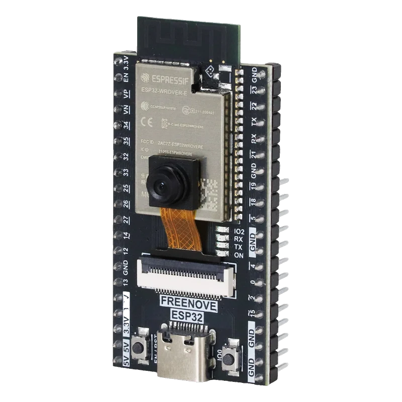
The Freenove ESP32-WROVER board carries Espressif's ESP32-WROVER-E module: two cores at up to 240 MHz, Wi-Fi, Bluetooth 4.2 (Classic and LE), 4 MB flash and 8 MB PSRAM (Freenove FNK0060 product page; ESP32-WROVER-E datasheet v2.4, p. 3). It adds a camera connector wired like Espressif's WROVER-KIT, a microSD slot in 1-bit mode, a CH340 USB-to-serial bridge and a blue LED on GPIO2 (Freenove pinout V3.0; C tutorial, p. 5). All I/O is 3.3 V; GPIO34 to 39 are input only, and GPIO16 and GPIO17 are not broken out because the PSRAM uses them.
Freenove's board is the ESP32 found in many starter kits: a classic ESP32 on the WROVER-E module, so it has the original chip's dual Xtensa LX6 cores, Bluetooth Classic and LE, two DACs and ten touch pins, plus 8 MB of PSRAM for camera frame buffers (ESP32-WROVER-E datasheet v2.4, p. 3). Freenove now sells it as the ESP32 DEV CAM with an OV2640 camera and a 1 GB card.
Both 20-pin headers are labelled with GPIO numbers. The camera connector uses GPIO4, 5, 18, 19, 21, 22, 23, 25, 26, 27, 34, 35, 36 and 39, the same assignment as Espressif's ESP-WROVER-KIT, so camera sketches use the CAMERA_MODEL_WROVER_KIT pin set; the microSD slot uses GPIO14 (CLK), GPIO15 (CMD) and GPIO2 (DATA) in 1-bit SDMMC mode (Freenove pinout V3.0).
USB goes through a CH340 bridge on GPIO1 and GPIO3, with TX and RX LEDs beside it (Freenove C tutorial, CH340 chapter; pinout V3.0). If an upload ever stalls on Connecting, hold BOOT (GPIO0) while it starts. Select ESP32 Wrover Module in Arduino and enable PSRAM for camera sketches.
Freenove ESP32-WROVER Board pinout
| Pin | Function | Type |
|---|---|---|
| 3V3 | 3.3 V3.3 V | power out |
| EN | Reset, CHIP_PU3.3 V | input |
| 36 | GPIO36, ADC1_CH0, Sensor_VP, Camera Y63.3 V only | input |
| 39 | GPIO39, ADC1_CH3, Sensor_VN, Camera Y73.3 V only | input |
| 34 | GPIO34, ADC1_CH6, Camera Y83.3 V only | input |
| 35 | GPIO35, ADC1_CH7, Camera Y93.3 V only | input |
| 32 | GPIO32, ADC1_CH4, Touch 9, PWM3.3 V only | bidirectional |
| 33 | GPIO33, ADC1_CH5, Touch 8, PWM3.3 V only | bidirectional |
| 25 | GPIO25, DAC1, ADC2_CH8, Camera VSYNC, PWM3.3 V only | bidirectional |
| 26 | GPIO26, DAC2, ADC2_CH9, Camera SIOD, PWM3.3 V only | bidirectional |
| 27 | GPIO27, ADC2_CH7, Touch 7, Camera SIOC, PWM3.3 V only | bidirectional |
| 14 | GPIO14, ADC2_CH6, Touch 6, HSPI CLK, SD CLK, PWM3.3 V only | bidirectional |
| 12 | GPIO12, ADC2_CH5, Touch 5, HSPI MISO, PWM3.3 V only | bidirectional |
| GND | GND | passive |
| 13 | GPIO13, ADC2_CH4, Touch 4, HSPI MOSI, PWM3.3 V only | bidirectional |
| 3V3 | 3.3 V3.3 V | power out |
| 3V3 | 3.3 V3.3 V | power out |
| 3V3 | 3.3 V3.3 V | power out |
| 5V | 5 V5 V | power in |
| 5V | 5 V5 V | power in |
| GND | GND | passive |
| 23 | GPIO23, VSPI MOSI, Camera HREF, PWM3.3 V only | bidirectional |
| 22 | GPIO22, I2C SCL, Camera PCLK, I2S DIN, PWM3.3 V only | bidirectional |
| 1 | GPIO1, UART0 TX3.3 V only | output |
| 3 | GPIO3, UART0 RX3.3 V only | input |
| 21 | GPIO21, I2C SDA, Camera XCLK, PWM3.3 V only | bidirectional |
| GND | GND | passive |
| 19 | GPIO19, VSPI MISO, Camera Y5, PWM3.3 V only | bidirectional |
| 18 | GPIO18, VSPI CLK, Camera Y4, PWM3.3 V only | bidirectional |
| 5 | GPIO5, VSPI CS, Camera Y3, PWM3.3 V only | bidirectional |
| GND | GND | passive |
| GND | GND | passive |
| 4 | GPIO4, ADC2_CH0, Touch 0, Camera Y2, PWM3.3 V only | bidirectional |
| 0 | GPIO0, ADC2_CH1, Touch 1, BOOT button3.3 V only | bidirectional |
| 2 | GPIO2, ADC2_CH2, Touch 2, LED, SD DATA, PWM3.3 V only | bidirectional |
| 15 | GPIO15, ADC2_CH3, Touch 3, HSPI CS, SD CMD, PWM3.3 V only | bidirectional |
| GND | GND | passive |
| GND | GND | passive |
| GND | GND | passive |
| GND | GND | passive |
Freenove ESP32-WROVER Board code
Every example here compiles for its board.
// Freenove ESP32-WROVER Board on Freenove ESP32-WROVER Board: wiring and a free simulation at https://www.tinkered.ai/components/freenove-esp32-wrover
// Freenove ESP32-WROVER board: Wi-Fi scan, blue LED on GPIO2 lit while scanning,
// and a reading of GPIO32 (ADC1, safe with Wi-Fi on). Serial Monitor at 115200.
#include <WiFi.h>

const int LED_PIN = 2;   // blue LED, HIGH = on
const int ADC_PIN = 32;  // ADC1_CH4, free even with the camera fitted

void setup() {
  Serial.begin(115200);
  pinMode(LED_PIN, OUTPUT);
  WiFi.mode(WIFI_STA);
  WiFi.disconnect();
  delay(100);
  Serial.println("Freenove ESP32-WROVER Wi-Fi scan");
  Serial.printf("PSRAM: %u bytes\n", (unsigned)ESP.getPsramSize());
}

void loop() {
  digitalWrite(LED_PIN, HIGH);
  int n = WiFi.scanNetworks();
  digitalWrite(LED_PIN, LOW);
  if (n <= 0) {
    Serial.println("No networks found");
  } else {
    Serial.printf("%d networks found:\n", n);
    for (int i = 0; i < n; i++) {
      Serial.printf("%2d  %-32s  %4d dBm  ch %2d  %s\n", i + 1, WiFi.SSID(i).c_str(), (int)WiFi.RSSI(i),
                    (int)WiFi.channel(i), WiFi.encryptionType(i) == WIFI_AUTH_OPEN ? "open" : "secured");
    }
  }
  WiFi.scanDelete();
  Serial.printf("GPIO32: %d mV\n\n", (int)analogReadMilliVolts(ADC_PIN));
  delay(10000);
}
Before you wire it
- Select ESP32 Wrover Module (or enable PSRAM) so the 8 MB PSRAM is usable; camera sketches need it.
- Use the CAMERA_MODEL_WROVER_KIT pin set for the camera connector on this board.
- Keep GPIO12 low and GPIO0 high at reset to boot your sketch (ESP32 datasheet pp. 22 to 23).
- Read analog signals on GPIO32 to GPIO39 (ADC1) in Wi-Fi sketches; ADC2 pins fail while Wi-Fi runs (ESP-IDF ADC guide).
- Install the CH340 driver if no serial port appears (Freenove C tutorial, CH340 chapter).
- Never use GPIO34, 35, 36 or 39 as outputs: they are input only with no internal pull-ups.
- Never use the camera's pins, including the default I2C pins GPIO21 and GPIO22, for other parts while the camera runs.
- Never apply 5 V to any GPIO; the ESP32's I/O is 3.3 V.
- Never pull GPIO12 high at reset with a sensor or module: the chip then selects 1.8 V flash and fails to boot.
- With the camera fitted, the only free GPIOs are GPIO0, 2, 12, 13, 14, 15, 32 and 33, and the microSD slot uses 2, 14 and 15. Plan I2C sensors on GPIO32 and GPIO33 with Wire.begin(32, 33) or similar.
- GPIO25 and GPIO26 are the ESP32's two 8-bit DACs, but on this board they are also the camera's VSYNC and SIOD lines.
- GPIO16 and GPIO17 are reserved for the PSRAM on WROVER modules (Espressif ESP-WROVER-KIT guide) and do not reach the headers.
- The headers carry three 3.3 V pins and two 5 V pins at the USB end, handy for powering several sensors on a breadboard.
Specifications
- Module and cores
- ESP32-WROVER-E (ESP32-D0WD-V3): dual-core Xtensa LX6, CPU clock adjustable from 80 to 240 MHzEspressif ESP32-WROVER-E datasheet v2.4, p. 3; Freenove FNK0060 product page
- Memory
- 520 KB SRAM in the ESP32; 4 MB flash and 8 MB PSRAM in the moduleFreenove FNK0060 product page; ESP32 datasheet v5.3, p. 4; ESP32-WROVER-E datasheet v2.4, p. 3
- Radios
- Wi-Fi 802.11 b/g/n 2.4 GHz and Bluetooth 4.2 (Classic and LE); PCB antennaFreenove FNK0060 product page; Espressif ESP32-WROVER-E datasheet v2.4
- I/O voltage
- 3.3 V logic; ESP32 power pins allowed at most 3.6 V, so pins are not 5 V tolerantEspressif ESP32 datasheet v5.3, p. 51
- GPIO current
- 40 mA source (20 mA on VDD_SDIO pins) and 28 mA sink typical per pin at maximum drive; 1200 mA cumulative IO output currentEspressif ESP32 datasheet v5.3, pp. 51 to 52
- USB
- CH340 USB-to-serial bridge on UART0 (GPIO1 TX, GPIO3 RX); needs the CH340 driver on some systemsFreenove C tutorial, CH340 chapter, p. 5
- ADC
- Two 12-bit SAR ADCs, 18 channels on the ESP32; ADC1 on GPIO32 to 39 works with Wi-Fi, ADC2 does notESP32 datasheet v5.3, p. 43; ESP-IDF ADC oneshot guide
- Camera and microSD
- Camera connector on GPIO4, 5, 18, 19, 21, 22, 23, 25, 26, 27, 34, 35, 36, 39; microSD on GPIO14 (CLK), 15 (CMD), 2 (DATA)Freenove ESP32 WROVER pinout V3.0
- LEDs and buttons
- Blue LED on GPIO2; TX, RX and power LEDs; EN/RST and BOOT (GPIO0) buttonsFreenove ESP32 WROVER pinout V3.0
From the Freenove ESP32 WROVER Board repository: pinout V3.0 and C tutorial, published by Freenove (ESP32-WROVER-E module by Espressif).
Common mistakes
Camera init fails
The board uses the WROVER-KIT camera pin assignment, not the AI-Thinker one. Select CAMERA_MODEL_WROVER_KIT, enable PSRAM, and check the ribbon is fully inserted with the latch closed.
I2C sensor stops the camera
The ESP32's default I2C pins, GPIO21 and GPIO22, are the camera's XCLK and PCLK here. Move the sensor's I2C to GPIO32 and GPIO33 with Wire.begin(32, 33).
analogRead() fails with Wi-Fi on
GPIO0, 2, 4, 12 to 15 and 25 to 27 are ADC2 channels, which the Wi-Fi driver also uses. Use GPIO32 to GPIO39 for analog signals in connected projects.
No serial port appears
The CH340 bridge needs WCH's driver on older Windows and some macOS versions, and a charge-only cable shows nothing. Freenove ships the drivers in its repository's CH340 folder.
Freenove ESP32-WROVER Board questions
Which board do I select in the Arduino IDE?
ESP32 Wrover Module, which enables PSRAM. Freenove's own tutorial uses it for every example, including the camera web server.
What is the difference between WROVER and WROOM?
Both use the classic ESP32 chip; the WROVER module adds PSRAM, 8 MB on the WROVER-E (datasheet v2.4, p. 3), and uses GPIO16 and GPIO17 for it. That memory is what camera streaming and large buffers need; a WROOM board like the DevKit V1 has none but keeps GPIO16 and 17.
Which pins are free when the camera is connected?
GPIO0, 2, 12, 13, 14, 15, 32 and 33 (Freenove pinout V3.0). Of those, 0, 2, 12 and 15 are strapping pins and 2, 14, 15 serve the microSD slot, so GPIO13, 32 and 33 are the safest.
Does it have Bluetooth Classic?
Yes. The classic ESP32 on the WROVER-E module has Bluetooth 4.2 Classic and LE, so BluetoothSerial works, unlike on the ESP32-S2, S3, C3 or C6.
Freenove WROVER or AI-Thinker ESP32-CAM?
Both pair an ESP32 with PSRAM and an OV2640. The Freenove board has USB with auto-reset, more header pins and breadboard headers; the ESP32-CAM is smaller but needs a USB-serial adapter and leaves very few pins free.
Build something with the Freenove ESP32-WROVER Board
- Build this
Camera web server
Stream the OV2640 to a browser and save snapshots to the microSD card.
- Build this
Bluetooth serial bridge
Send sensor readings to a phone over Bluetooth Classic serial.
This page as plain Markdown, for ChatGPT, Claude or your own agent. /components/freenove-esp32-wrover.md