ESP32-CAM (AI-Thinker)
Ai-Thinker's tiny ESP32 camera board: an ESP32 with 4 MB PSRAM, an OV2640 camera, a microSD slot and a flash LED, programmed through an external USB-serial adapter.
- Chip and coresESP32 (Ai-Thinker ESP32-S): dual-core 32-bit, up to 240 MHz, 600 DMIPS
- Memory520 KB internal SRAM plus 4 MB external PSRAM; 32 Mbit (4 MB) SPI flash by default
- RadiosWi-Fi 802.11b/g/n 2.4 GHz and Bluetooth 4.2 BR/EDR and BLE; onboard PCB antenna, 2 dBi
- CameraOV2640 (or OV7670) on the camera connector; JPEG output is OV2640 only. Measured 6 to 8 fps in JPEG from QQVGA to SVGA at 20 MHz XCLK
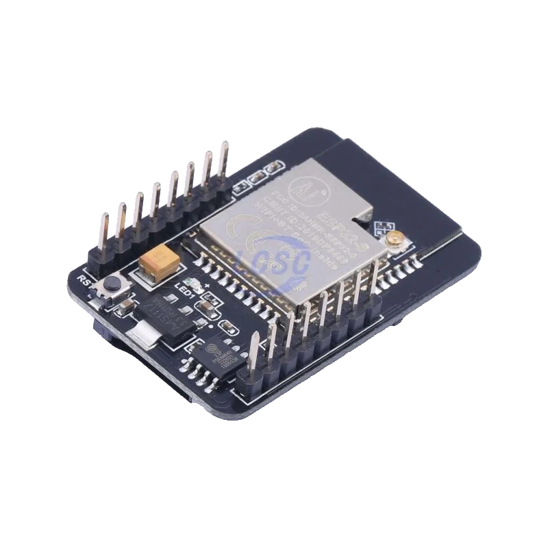
The AI-Thinker ESP32-CAM is a 27 x 40.5 mm board with an ESP32 (two cores at 240 MHz), 520 KB SRAM plus 4 MB PSRAM, 4 MB (32 Mbit) flash, an OV2640 camera, a microSD slot and a flash LED on GPIO4 (Ai-Thinker ESP32-CAM specification V1.0, pp. 1 to 3). It has no USB port: you flash it through a 3.3 V USB-serial adapter or the ESP32-CAM-MB base, with GPIO0 tied to GND during reset. It runs from 5 V and draws about 180 mA, or 310 mA with the flash LED at full brightness (spec p. 2), so weak USB ports and thin wires make it brown out.
The ESP32-CAM is the cheapest way to put a Wi-Fi camera on a project: Ai-Thinker's ESP32-S module, a 2 MP OmniVision OV2640 on a 24-pin ribbon connector, a microSD (TF) slot and a white flash LED, all on a 16-pin DIP footprint of 27 x 40.5 x 4.5 mm (Ai-Thinker spec V1.0, pp. 1 to 2). It streams JPEG from the camera to a browser and can save photos to the card.
The price of that density is the pin budget. The camera takes GPIO0, 5, 18, 19, 21, 22, 23, 25, 26, 27, 32, 34, 35, 36 and 39, and the microSD slot takes GPIO2, 4, 12, 13, 14 and 15 in 4-bit mode (spec p. 3). Only 9 I/O reach the header (spec p. 2), and most of them are shared with the card slot or are ESP32 strapping pins, so plan for one or two extra signals at most, or run the card in 1-bit mode to free GPIO4, 12 and 13.
There is no USB connector or USB-serial chip on the board. Use a 3.3 V FTDI-style adapter on U0TXD/U0RXD, or the ESP32-CAM-MB base that adds a CH340 and auto-reset. For Arduino, select AI Thinker ESP32-CAM, or the ESP32 Wrover Module with PSRAM enabled, and use the camera pin set named CAMERA_MODEL_AI_THINKER.
ESP32-CAM (AI-Thinker) pinout
| Pin | Function | Type |
|---|---|---|
| IO4 | GPIO4, Flash LED, SD DATA1, ADC2_CH0, Touch, PWM3.3 V only | bidirectional |
| IO2 | GPIO2, SD DATA0, ADC2_CH2, Touch, PWM3.3 V only | bidirectional |
| IO14 | GPIO14, SD CLK, HSPI CLK, ADC2_CH6, Touch, PWM3.3 V only | bidirectional |
| IO15 | GPIO15, SD CMD, HSPI CS, ADC2_CH3, Touch, PWM3.3 V only | bidirectional |
| IO13 | GPIO13, SD DATA3, HSPI MOSI, ADC2_CH4, Touch, PWM3.3 V only | bidirectional |
| IO12 | GPIO12, SD DATA2, HSPI MISO, ADC2_CH5, Touch, PWM3.3 V only | bidirectional |
| GND | GND | passive |
| 5V | 5 V5 V | power in |
| 3V3 | 3.3 V3.3 V | power in |
| IO16 | GPIO16, PSRAM CS3.3 V only | bidirectional |
| IO0 | GPIO0, Camera XCLK, Boot strap3.3 V only | bidirectional |
| GND | GND | passive |
| VCC | Supply out | power out |
| U0R | GPIO3, UART0 RX3.3 V only | input |
| U0T | GPIO1, UART0 TX3.3 V only | output |
| GND | GND | passive |
ESP32-CAM (AI-Thinker) code
Every example here compiles for its board.
// ESP32-CAM (AI-Thinker) on ESP32-CAM (AI-Thinker): wiring and a free simulation at https://www.tinkered.ai/components/esp32-cam
// ESP32-CAM (AI-Thinker): a tiny web server that sets the flash LED on GPIO4.
// The board starts its own Wi-Fi network; join it and open http://192.168.4.1
// Upload: GPIO0 to GND, press RESET, upload, then remove the jumper and press RESET.
#include <WiFi.h>
#include <WebServer.h>

const char *AP_SSID = "ESP32-CAM";
const char *AP_PASS = "esp32cam123";  // at least 8 characters
const int FLASH_LED = 4;              // white flash LED, active high

WebServer server(80);
int level = 0;  // 0 to 255; keep it low, the LED is very bright and gets hot

void sendPage() {
  String html = "<!doctype html><html><head><meta name=viewport content='width=device-width'>"
                "<title>ESP32-CAM flash</title></head><body style='font-family:sans-serif'>"
                "<h1>ESP32-CAM flash LED</h1><p>Level: " + String(level) + "</p>"
                "<p><a href='/set?l=0'>Off</a> | <a href='/set?l=10'>Dim</a> | "
                "<a href='/set?l=60'>Medium</a> | <a href='/set?l=255'>Full</a></p></body></html>";
  server.send(200, "text/html", html);
}

void handleSet() {
  if (server.hasArg("l")) {
    level = constrain(server.arg("l").toInt(), 0, 255);
    analogWrite(FLASH_LED, level);
    Serial.printf("Flash level %d\n", level);
  }
  sendPage();
}

void setup() {
  Serial.begin(115200);
  pinMode(FLASH_LED, OUTPUT);
  analogWrite(FLASH_LED, 0);
  WiFi.mode(WIFI_AP);
  WiFi.softAP(AP_SSID, AP_PASS);
  Serial.print("Join Wi-Fi ");
  Serial.print(AP_SSID);
  Serial.print(" and open http://");
  Serial.println(WiFi.softAPIP());
  server.on("/", sendPage);
  server.on("/set", handleSet);
  server.begin();
}

void loop() {
  server.handleClient();
}
Before you wire it
- Power it from a solid 5 V supply on the 5V pin that can give at least 500 mA: the board draws 180 mA, 310 mA with the flash LED at full (spec p. 2), and Wi-Fi bursts add peaks.
- Use a 3.3 V USB-serial adapter: its TX to U0R, its RX to U0T, and GND to GND.
- Tie GPIO0 to GND and press RESET to flash; remove the jumper and press RESET again to run (ESP32 datasheet p. 23).
- Enable PSRAM and pick the AI Thinker camera pin set (CAMERA_MODEL_AI_THINKER) in camera sketches.
- Keep GPIO12 low or floating at power-up: it is MTDI, which selects the flash voltage (ESP32 datasheet p. 22).
- Never run the flash LED at full brightness for long: it pulls 130 mA more (spec p. 2) and heats the board.
- Never feed 5 V logic into any GPIO; the ESP32's I/O is 3.3 V.
- Never use GPIO16 or the camera's pins for your own parts while the camera or PSRAM is in use.
- Never expect analogRead() on the header pins with Wi-Fi on: all of them are ADC2 channels, which Wi-Fi also uses (ESP-IDF ADC oneshot guide).
- Ai-Thinker's minimum system puts 10 µF and 0.1 µF from 5V to GND at the board and leaves GPIO0 floating to run (spec p. 4). Add a 470 µF electrolytic at the 5V pin if you see resets when Wi-Fi starts.
- Running the microSD card in 1-bit mode (SD_MMC.begin("/sdcard", true)) leaves GPIO4, GPIO12 and GPIO13 free and stops the flash LED blinking with card access.
- The ESP32-CAM-MB programmer base adds USB, a CH340 and auto-reset, so you no longer need the GPIO0 jumper.
- The PCB antenna sits at the end opposite the camera connector; keep metal, batteries and ground planes away from it when you build it into a case.
Specifications
- Chip and cores
- ESP32 (Ai-Thinker ESP32-S): dual-core 32-bit, up to 240 MHz, 600 DMIPSAi-Thinker ESP32-CAM specification V1.0, p. 1
- Memory
- 520 KB internal SRAM plus 4 MB external PSRAM; 32 Mbit (4 MB) SPI flash by defaultAi-Thinker ESP32-CAM specification V1.0, p. 2
- Radios
- Wi-Fi 802.11b/g/n 2.4 GHz and Bluetooth 4.2 BR/EDR and BLE; onboard PCB antenna, 2 dBiAi-Thinker ESP32-CAM specification V1.0, p. 2
- Camera
- OV2640 (or OV7670) on the camera connector; JPEG output is OV2640 only. Measured 6 to 8 fps in JPEG from QQVGA to SVGA at 20 MHz XCLKAi-Thinker ESP32-CAM specification V1.0, pp. 1 to 3
- Supply and current
- 5 V supply; 180 mA at 5 V with the flash off, 310 mA with the flash LED at maximum; deep sleep down to 6 mA at 5 V (board total)Ai-Thinker ESP32-CAM specification V1.0, p. 2
- I/O voltage
- 3.3 V logic; ESP32 power pins allowed at most 3.6 V, so GPIOs are not 5 V tolerantEspressif ESP32 datasheet v5.3, p. 51
- GPIO current
- 40 mA source, 28 mA sink typical per pin at maximum drive; 1200 mA cumulative IO output currentEspressif ESP32 datasheet v5.3, pp. 51 to 52
- Flash LED and microSD
- Flash LED on GPIO4 (also SD DATA1); microSD up to 4 GB on CLK GPIO14, CMD GPIO15, DATA0 to DATA3 on GPIO2, 4, 12, 13Ai-Thinker ESP32-CAM specification V1.0, pp. 2 to 3
- Programming
- No USB: UART at 115200 baud by default on U0TXD/U0RXD; GPIO0 low at reset enters download modeAi-Thinker ESP32-CAM specification V1.0, pp. 2, 4; ESP32 datasheet v5.3, p. 23
- Size
- 27 x 40.5 x 4.5 mm, DIP-16, 10 gAi-Thinker ESP32-CAM specification V1.0, pp. 2 to 3
From the Ai-Thinker ESP32-CAM documentation page and module specification V1.0, published by Ai-Thinker (ESP32 by Espressif).
Common mistakes
Brownout detector was triggered
The ESP32 resets when its supply sags, which happens when Wi-Fi and the camera start together on a weak USB port, a long thin cable or the FTDI adapter's own 3.3 V. Power the 5V pin from a 5 V supply rated 1 A or more, with short thick wires.
Failed to connect: wrong boot mode
The board only accepts code in download mode: GPIO0 must be on GND while it resets. Without the ESP32-CAM-MB base there is no auto-reset, so press RESET with the jumper in place, upload, then remove it and reset again.
Camera init failed with error 0x105
Usually the wrong camera pin set or a loose ribbon. Select CAMERA_MODEL_AI_THINKER, enable PSRAM, and reseat the OV2640 ribbon with its latch closed.
Using GPIO12 for a sensor that pulls high
GPIO12 is the ESP32's MTDI strap: high at reset it sets the flash supply to 1.8 V and the board will not boot (ESP32 datasheet p. 22). Use a pin that is low at reset, or move the sensor.
ESP32-CAM (AI-Thinker) questions
How do I program the ESP32-CAM without a USB port?
Use a 3.3 V USB-serial adapter (FTDI, CP2102 or CH340) on U0R and U0T, power the 5V pin, hold GPIO0 to GND and press RESET, then upload. The ESP32-CAM-MB base board does all of this for you with a micro-USB connector and auto-reset.
Which pins are free on the ESP32-CAM?
Very few. The camera takes 15 GPIOs, the microSD slot takes GPIO2, 4, 12, 13, 14 and 15, and GPIO16 belongs to the PSRAM (Ai-Thinker spec p. 3). Without the card you can use GPIO12 to 15 and GPIO2; with the card in 1-bit mode, GPIO4, 12 and 13 come back.
Why does my ESP32-CAM keep rebooting?
Almost always power. The board needs about 180 mA plus Wi-Fi peaks, and 310 mA with the flash on (spec p. 2), so a USB-serial adapter's 3.3 V pin or a weak port browns it out. Feed 5 V from a proper supply into the 5V pin.
What resolution and frame rate does the ESP32-CAM manage?
The OV2640 is a 1600 x 1200 sensor. Ai-Thinker measured 6 fps at QQVGA up to 8 fps at SVGA in JPEG over Wi-Fi with a 20 MHz XCLK (spec p. 3); smaller frames and a good Wi-Fi link stream faster.
Is the flash LED on GPIO4 controllable?
Yes: GPIO4 drives it, active high, and PWM (analogWrite or ledc) sets its brightness. It also shares GPIO4 with SD DATA1, so it flickers during 4-bit card access.
Build something with the ESP32-CAM (AI-Thinker)
- Build this
Wi-Fi security camera
Stream video to a browser and save a photo to the microSD card when motion is detected.
- Build this
Doorbell snapshot
Take a picture when a button is pressed and send it to a phone.
This page as plain Markdown, for ChatGPT, Claude or your own agent. /components/esp32-cam.md