Arduino Nano ESP32
Arduino's Nano-format board built on an ESP32-S3 (u-blox NORA-W106 module): dual-core 240 MHz, Wi-Fi, Bluetooth LE, native USB-C and 3.3 V pins in the classic Nano layout.
- Chip and coresESP32-S3 in a u-blox NORA-W106-10B module: dual-core Xtensa LX7 up to 240 MHz
- Memory512 kB SRAM, 384 kB ROM, 8 MB octal PSRAM in the module, 16 MB external flash (GD25B128EWIGR)
- RadiosWi-Fi 4 (802.11b/g/n) 2.4 GHz and Bluetooth LE 5.0 with a built-in antenna; no Bluetooth Classic
- I/O voltage3.3 V on every digital and analog pin; higher voltages risk damaging the board
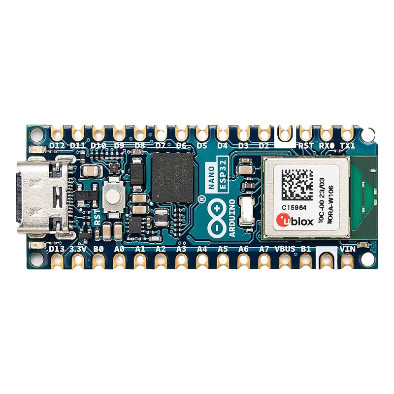
The Arduino Nano ESP32 puts an ESP32-S3 (inside a u-blox NORA-W106-10B module) on the 18 x 45 mm Nano footprint, with two LX7 cores at up to 240 MHz, 512 kB SRAM, 8 MB PSRAM, 16 MB flash, Wi-Fi 4 and Bluetooth LE 5.0 (Arduino ABX00083 datasheet, pp. 2, 8 to 9, 12). Unlike the classic Nano its pins are 3.3 V only, it has no 5V pin (VBUS gives 5 V only on USB power), and VIN takes 6 to 21 V through an MP2322 buck converter (datasheet pp. 5, 12 to 14). Pins are numbered D0 to D13 and A0 to A7 as on any Nano, mapped to ESP32-S3 GPIOs by the Arduino core.
The Nano ESP32 is Arduino's way into the ESP32 world without leaving the Nano form factor: shields and carrier boards made for the Nano fit, and sketches keep the D2, D13 and A0 names because the Arduino ESP32 core maps them to the real GPIOs (D2 is GPIO5, D13 is GPIO48, A0 is GPIO1; Arduino Nano ESP32 cheat sheet, ESP32 Pin Map). A Tools menu option switches to raw GPIO numbers for code written for other ESP32 boards.
Inside the NORA-W106-10B module are an ESP32-S3 with two Xtensa LX7 cores at up to 240 MHz, 512 kB of SRAM, 384 kB of ROM and 8 MB of octal PSRAM, plus a built-in antenna; a separate GD25B128 chip adds 16 MB of flash (datasheet pp. 8 to 9, 12). The radio does Wi-Fi 4 (802.11b/g/n, 2.4 GHz) and Bluetooth LE 5.0, but not Bluetooth Classic.
USB-C goes straight to the ESP32-S3's native USB, so there is no USB-to-serial chip or driver to install. Power comes from USB (4.8 to 5.5 V) or the VIN pin (6 to 21 V), both stepped down to 3.3 V by an MP2322GQH buck converter (datasheet pp. 5, 12). Every I/O pin is 3.3 V: treat it like any ESP32, not like a 5 V Nano.
Arduino Nano ESP32 pinout
| Pin | Function | Type |
|---|---|---|
| D13 | GPIO48, SPI SCK, LED_BUILTIN, PWM3.3 V only | bidirectional |
| 3.3V | 3.3 V3.3 V | power out |
| B0 | GPIO46, Boot strap3.3 V only | input |
| A0 | GPIO1, ADC1_CH0, Touch, PWM3.3 V only | bidirectional |
| A1 | GPIO2, ADC1_CH1, Touch, PWM3.3 V only | bidirectional |
| A2 | GPIO3, ADC1_CH2, Touch, PWM3.3 V only | bidirectional |
| A3 | GPIO4, ADC1_CH3, Touch, PWM3.3 V only | bidirectional |
| A4 | GPIO11, ADC2, I2C SDA, PWM3.3 V only | bidirectional |
| A5 | GPIO12, ADC2, I2C SCL, PWM3.3 V only | bidirectional |
| A6 | GPIO13, ADC2, PWM3.3 V only | bidirectional |
| A7 | GPIO14, ADC2, PWM3.3 V only | bidirectional |
| VBUS | 5 V from USB5 V | power out |
| B1 | GPIO0, Boot strap3.3 V only | input |
| GND | GND | passive |
| VIN | 6 to 21 V in6 to 21 V | power in |
| D12 | GPIO47, SPI MISO, PWM3.3 V only | bidirectional |
| D11 | GPIO38, SPI MOSI, PWM3.3 V only | bidirectional |
| D10 | GPIO21, SPI SS, PWM, I2S SD in (core default)3.3 V only | bidirectional |
| D9 | GPIO18, PWM, I2S SD out (core default)3.3 V only | bidirectional |
| D8 | GPIO17, PWM, I2S FS (core default)3.3 V only | bidirectional |
| D7 | GPIO10, PWM, Touch, I2S SCK (core default)3.3 V only | bidirectional |
| D6 | GPIO9, PWM, Touch3.3 V only | bidirectional |
| D5 | GPIO8, PWM, Touch3.3 V only | bidirectional |
| D4 | GPIO7, PWM, Touch3.3 V only | bidirectional |
| D3 | GPIO6, PWM, Touch3.3 V only | bidirectional |
| D2 | GPIO5, PWM, Touch3.3 V only | bidirectional |
| GND | GND | passive |
| RST | Reset | input |
| RX0 | GPIO44, UART RX (Serial0), PWM3.3 V only | bidirectional |
| TX1 | GPIO43, UART TX (Serial0), PWM3.3 V only | bidirectional |
Arduino Nano ESP32 code
Every example here compiles for its board.
// Arduino Nano ESP32 on Arduino Nano ESP32: wiring and a free simulation at https://www.tinkered.ai/components/arduino-nano-esp32
// Arduino Nano ESP32: Wi-Fi scan, RGB LED status and an A0 reading.
// The RGB LED pins are active LOW (LOW = on). Serial is the native USB port at 115200.
#include <WiFi.h>

void rgb(bool r, bool g, bool b) {
  digitalWrite(LED_RED, r ? LOW : HIGH);
  digitalWrite(LED_GREEN, g ? LOW : HIGH);
  digitalWrite(LED_BLUE, b ? LOW : HIGH);
}

void setup() {
  Serial.begin(115200);
  unsigned long start = millis();
  while (!Serial && millis() - start < 3000) {
  }
  pinMode(LED_RED, OUTPUT);
  pinMode(LED_GREEN, OUTPUT);
  pinMode(LED_BLUE, OUTPUT);
  rgb(false, false, false);
  WiFi.mode(WIFI_STA);
  WiFi.disconnect();
  Serial.println("Nano ESP32 Wi-Fi scan");
}

void loop() {
  rgb(false, false, true);  // blue while scanning
  int n = WiFi.scanNetworks();
  if (n <= 0) {
    Serial.println("No networks found");
    rgb(true, false, false);
  } else {
    Serial.print(n);
    Serial.println(" networks found:");
    for (int i = 0; i < n; i++) {
      Serial.print("  ");
      Serial.print(WiFi.SSID(i));
      Serial.print("  ");
      Serial.print(WiFi.RSSI(i));
      Serial.print(" dBm  ");
      Serial.println(WiFi.encryptionType(i) == WIFI_AUTH_OPEN ? "open" : "secured");
    }
    rgb(false, true, false);
  }
  WiFi.scanDelete();

  // A0 is on ADC1, so it reads fine while Wi-Fi is on. Keep it between 0 and 3.3 V.
  int mv = analogReadMilliVolts(A0);
  Serial.print("A0: ");
  Serial.print(mv);
  Serial.println(" mV");
  Serial.println();
  delay(10000);
}
Before you wire it
- Keep every pin at 3.3 V or below (datasheet p. 13); use a level shifter for 5 V modules that were fine on a classic Nano.
- Feed VIN with 6 to 21 V, and the USB-C port with no more than 5 V (datasheet pp. 5, 12 to 13).
- Take 5 V for a module from VBUS only when the board runs on USB; on VIN power VBUS stays off (datasheet p. 14).
- Write the RGB LED pins LOW to light them: LED_RED, LED_GREEN and LED_BLUE are active low (cheat sheet, RGB).
- Use A0 to A3 (ADC1) for analog readings in Wi-Fi sketches; A4 to A7 are on ADC2, which Wi-Fi also uses (cheat sheet, Analog).
- Install the board package named Arduino ESP32 Boards (the Nano ESP32 entry), not only Espressif's package, to keep the D and A pin names.
- Never drop it into a classic Nano carrier that expects +5V and RESET on the analog side: there the Nano ESP32 has VBUS (5 V on USB power only) and B1 (GPIO0, a boot strap).
- Never source more than 40 mA or sink more than 28 mA on one pin (datasheet p. 14).
- Never tie B0 or B1 to anything while you run sketches: they are the ESP32-S3 boot straps and share GPIOs with the RGB LED.
- D13 is both SPI SCK and LED_BUILTIN (GPIO48); an SPI display or SD card makes the orange LED flicker, which is normal.
- The MP2322 buck converter is efficient across VIN (above 90 % at 4.5 V, 85 to 90 % at 12 V, under 85 % at 18 V, datasheet p. 13), so a 2S lithium pack or a 12 V adapter on VIN is fine.
- Pins can be numbered by Arduino name (default) or by GPIO number (Tools > Pin Numbering > By GPIO number). Code copied from other ESP32 boards often assumes GPIO numbers.
- I2S has no fixed pins, but the core's defaults are D7 (SCK), D8 (FS), D9 (SD out) and D10 (SD in).
Specifications
- Chip and cores
- ESP32-S3 in a u-blox NORA-W106-10B module: dual-core Xtensa LX7 up to 240 MHzArduino Nano ESP32 datasheet (ABX00083), pp. 2, 8
- Memory
- 512 kB SRAM, 384 kB ROM, 8 MB octal PSRAM in the module, 16 MB external flash (GD25B128EWIGR)Arduino Nano ESP32 datasheet, pp. 8 to 9, 12
- Radios
- Wi-Fi 4 (802.11b/g/n) 2.4 GHz and Bluetooth LE 5.0 with a built-in antenna; no Bluetooth ClassicArduino Nano ESP32 datasheet, p. 8; Nano ESP32 tech specs
- I/O voltage
- 3.3 V on every digital and analog pin; higher voltages risk damaging the boardArduino Nano ESP32 datasheet, p. 13 (Pin Voltage)
- GPIO current
- Up to 40 mA source and 28 mA sink per pinArduino Nano ESP32 datasheet, p. 14 (Pin Current)
- Power inputs
- USB-C 4.8 to 5.5 V, or VIN 6 to 21 V (7 V typical); both go through an MP2322GQH step-down converter to 3.3 V. No 5V pin: VBUS carries 5 V only when USB powers the boardArduino Nano ESP32 datasheet, pp. 5, 12 to 14
- USB
- USB-C to the ESP32-S3's native USB (no USB-serial bridge chip); do not feed more than 5 V into itArduino Nano ESP32 datasheet, p. 12
- ADC
- 8 analog inputs, 12-bit by default (0 to 4095); A0 to A3 on ADC1, A4 to A7 on ADC2, which Wi-Fi also usesArduino Nano ESP32 cheat sheet, Analog
- LEDs
- LED_BUILTIN on D13 (GPIO48, shared with SPI SCK); an RGB LED on GPIO46 (red), GPIO0 (green) and GPIO45 (blue), active lowArduino Nano ESP32 cheat sheet, RGB; arduino-esp32 nano_nora pins_arduino.h
- Board size
- 18 x 45 mm (Nano form factor)Arduino Nano ESP32 tech specs
From the Arduino Nano ESP32 product reference manual (ABX00083), published by Arduino (ESP32-S3 by Espressif, NORA-W106 module by u-blox).
Common mistakes
Wiring 5 V parts the way you did on a classic Nano
The classic Nano is a 5 V board; the Nano ESP32 is 3.3 V on every pin. A 5 V sensor output or an HC-SR04 echo line wired straight in can damage the ESP32-S3. Use a divider or a level shifter.
Board no longer shows up after an upload
Because USB is native, a crashing or HID sketch can take the port away. Double-tap the reset button: the green LED pulses slowly in Arduino bootloader mode and you can upload again (cheat sheet, Arduino Bootloader Mode).
analogRead() on A4 to A7 returns errors with Wi-Fi on
A4 to A7 belong to ADC2, which the Wi-Fi driver also uses, so reads can fail while Wi-Fi is active (cheat sheet, Analog). Move analog inputs to A0 to A3, and keep A4/A5 for I2C.
RGB LED colours look inverted
The LED is active low, so digitalWrite(LED_RED, HIGH) turns red off. Some boards from the first batch also swapped green and blue (cheat sheet, RGB).
Arduino Nano ESP32 questions
Is the Arduino Nano ESP32 5 V tolerant?
No. Arduino states that all digital and analog pins are 3.3 V and that higher voltages risk damaging the board (datasheet p. 13). It has no 5V pin either; VBUS gives 5 V only while USB powers the board.
Which chip is on the Nano ESP32?
An ESP32-S3 inside a u-blox NORA-W106-10B module, with two LX7 cores at up to 240 MHz, 512 kB SRAM and 8 MB PSRAM, plus a 16 MB external flash chip (datasheet pp. 8 to 9, 12).
How do I get the Nano ESP32 into bootloader mode?
Double-tap the reset button; the RGB LED pulses green in Arduino bootloader mode (cheat sheet). For the ESP32-S3's ROM downloader, used to restore Arduino's bootloader, B1 is GPIO0: held low during reset it starts ROM boot mode.
Does the Nano ESP32 need a USB driver?
No. USB-C goes straight to the ESP32-S3's native USB, so there is no CH340 or CP210x chip (datasheet p. 12). Serial in a sketch is the USB port.
Nano ESP32 or Nano R4?
The Nano ESP32 has Wi-Fi, Bluetooth LE, two 240 MHz cores and 8 MB PSRAM, but 3.3 V pins. The Nano R4 keeps 5 V I/O and the Renesas RA4M1, with no radio. Pick the ESP32 for connected projects and the R4 for 5 V shields.
Build something with the Arduino Nano ESP32
- Build this
Arduino Cloud sensor dashboard
Send temperature and humidity to a dashboard over Wi-Fi and show the latest values on an OLED.
- Build this
BLE remote for a desk lamp
Control an LED strip's brightness from a phone over Bluetooth LE.
This page as plain Markdown, for ChatGPT, Claude or your own agent. /components/arduino-nano-esp32.md