Arduino Nano R4
The classic Nano footprint with a 48 MHz Arm Cortex-M4, 5 V I/O, USB-C and a Qwiic port.
- MicrocontrollerRenesas RA4M1 (R7FA4M1AB3CFM), Arm Cortex-M4 with FPU at 48 MHz
- Memory256 kB flash, 32 kB SRAM, 8 kB data flash (EEPROM)
- I/O voltage5 V (Qwiic connector at 3.3 V)
- VIN input6 V to 21 V, 7 V typical, through an MP2322 buck to 5 V
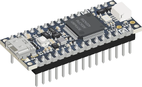
The Arduino Nano R4 is a Nano-sized board built on the Renesas RA4M1, a 48 MHz Arm Cortex-M4 with 256 kB flash and 32 kB SRAM, that runs its I/O at 5 V like the classic Nano (Arduino ABX00142 datasheet, p. 1). Power it over USB-C at 5 V or with 6 to 21 V on VIN (p. 9), wire parts to D0 to D13 and A0 to A7, and keep each pin under 8 mA (p. 10). I2C sits on A4/A5 as Wire, and the Qwiic connector is a second 3.3 V bus, Wire1 (p. 7).
The Arduino Nano R4 (SKU ABX00142, or ABX00143 with headers fitted) puts the Renesas RA4M1 microcontroller of the UNO R4 boards into the Nano form factor. The chip is a 48 MHz Arm Cortex-M4 with a floating point unit, 256 kB of flash, 32 kB of SRAM and 8 kB of data flash used as EEPROM (Arduino Nano R4 datasheet, pp. 1, 6). Arduino fixed its operating voltage at 5 V so the board stays compatible with 5 V Nano accessories and shields (p. 6).
The pinout follows the classic Nano: D0 to D13 on one edge, A0 to A7 with AREF, 3V3, 5V and VIN on the other, 2.54 mm apart on a 43.18 × 17.78 mm board (pp. 13, 17). Every exposed pin can act as a digital I/O, the eight analog inputs feed a 14-bit ADC, A0 carries a 12-bit DAC, A1 to A3 reach an on-chip op-amp, and D4/D5 carry a CAN controller that needs an external transceiver (pp. 5, 6, 13). A USB-C port powers and programs the board, and a Qwiic connector adds a 3.3 V I2C bus for Modulino and other Qwiic boards (pp. 6, 7).
Two differences catch people coming from the classic Nano. Each RA4M1 GPIO is rated for 8 mA (p. 10), so LED resistors grow and anything heavier goes through a transistor. And the board has its own built-in LED and an RGB LED (p. 8): in the Arduino core, LED_BUILTIN is a dedicated pin rather than D13, so D13 stays free for SPI's clock.
Arduino Nano R4 pinout
| Pin | Function | Type |
|---|---|---|
| D12 | PWM, SPI MISO, Digital5 V | bidirectional |
| D11 | PWM, SPI MOSI, Digital5 V | bidirectional |
| D10 | PWM, SPI CS, Digital5 V | bidirectional |
| D9 | PWM, Digital5 V | bidirectional |
| D8 | PWM, Digital5 V | bidirectional |
| D7 | PWM, Digital5 V | bidirectional |
| D6 | PWM, Digital5 V | bidirectional |
| D5 | PWM, CAN RX, Digital5 V | bidirectional |
| D4 | PWM, CAN TX, Digital5 V | bidirectional |
| D3 | PWM, Digital5 V | bidirectional |
| D2 | PWM, Digital5 V | bidirectional |
| GND_R | GND | power in |
| RST | Digital5 V | input |
| D0 | UART RX, PWM, Digital5 V | bidirectional |
| D1 | UART TX, PWM, Digital5 V | bidirectional |
| D13 | PWM, SPI SCK, Digital5 V | bidirectional |
| 3V3 | 3V3 (AP2112K output)3.3 V | power out |
| AREF | ADC5 V | input |
| A0 | ADC AN0, DAC, Digital5 V | bidirectional |
| A1 | ADC AN1, Digital5 V | bidirectional |
| A2 | ADC AN2, Digital5 V | bidirectional |
| A3 | ADC AN3, Digital5 V | bidirectional |
| A4 | ADC AN4, I2C SDA, PWM, Digital5 V | bidirectional |
| A5 | ADC AN5, I2C SCL, PWM, Digital5 V | bidirectional |
| A6 | ADC AN6, Digital5 V | bidirectional |
| A7 | ADC AN7, Digital5 V | bidirectional |
| 5V | 5V5 V | power out |
| BOOT | BOOT (B1 on the back, the RA4M1's MD) | input |
| GND_L | GND | power in |
| VIN | VIN (6-21 V) | power in |
Specifications
- Microcontroller
- Renesas RA4M1 (R7FA4M1AB3CFM), Arm Cortex-M4 with FPU at 48 MHzArduino Nano R4 datasheet (ABX00142), pp. 1, 6
- Memory
- 256 kB flash, 32 kB SRAM, 8 kB data flash (EEPROM)Arduino Nano R4 datasheet, p. 1
- I/O voltage
- 5 V (Qwiic connector at 3.3 V)Arduino Nano R4 datasheet, p. 10
- VIN input
- 6 V to 21 V, 7 V typical, through an MP2322 buck to 5 VArduino Nano R4 datasheet, p. 9
- USB-C input
- 4.8 V to 5.5 V, 500 mA maxArduino Nano R4 datasheet, p. 9
- Current per GPIO
- 8 mAArduino Nano R4 datasheet, p. 10
- Analog
- 8 inputs (A0 to A7), 14-bit ADC; 12-bit DAC on A0; op-amp on A1 (+), A2 (-), A3 (out)Arduino Nano R4 datasheet, pp. 5, 6, 13
- Buses
- UART (USB serial and Serial1 on D0/D1), I2C on A4/A5 and Qwiic, SPI on D10 to D13, CAN on D4 (TX) / D5 (RX)Arduino Nano R4 datasheet, pp. 5, 13
- Board size
- 43.18 × 17.78 mm, 2.54 mm pitch headersArduino Nano R4 datasheet, pp. 17, 18
- Operating temperature
- -40 °C to +85 °CArduino Nano R4 datasheet, p. 9
- Logic level
- 5 V
- Clock speed
- 48 MHz
- Flash
- 256 KB
- RAM
- 32 KB
- GPIO pins
- 21maker's datasheet, checked 29 Oct 2026
- ADC channels
- 8
- ADC resolution
- 14 bits
- PWM channels
- 6maker's datasheet, checked 29 Oct 2026
- Dimensions
- 43.18 × 17.78 × 13.31 mmmaker's datasheet, checked 29 Oct 2026
- Weight
- 4 g
From the Arduino's datasheet, published by Arduino.
Common mistakes
Expecting the onboard LED on D13
On the Nano R4 the built-in LED has its own pin: LED_BUILTIN in the Arduino core is not D13. Use LED_BUILTIN in code, and wire your own LED to D13 if you want one there.
Driving pins as hard as an old AVR Nano
The RA4M1's pins are rated for 8 mA (Nano R4 datasheet, p. 10). A 220 Ω LED resistor or a relay coil straight on a pin overloads it. Use about 390 Ω or more for LEDs and a transistor for anything heavier.
Putting a 3.3 V module on the 5 V header
The header pins swing to 5 V (p. 10), which can damage 3.3 V-only sensors and displays. Use a level shifter, or plug Qwiic boards into the 3.3 V Qwiic connector and talk to them through Wire1 (p. 7).
Lighting the RGB LED with HIGH
The RGB LED (LEDR, LEDG, LEDB) is wired active-low: digitalWrite(LEDR, LOW) turns red on and HIGH turns it off. Set the three pins HIGH in setup() to start with it dark.
Reaching for Wi-Fi or Bluetooth libraries
The Nano R4 has no radio. Code that includes WiFiS3 or ArduinoBLE will not work on it; pick the UNO R4 WiFi or an ESP32 board for wireless projects.
Arduino Nano R4 questions
Is the Arduino Nano R4 5 V or 3.3 V?
5 V. The RA4M1's operating voltage is fixed at 5 V and every header pin runs at that level; only the Qwiic connector is 3.3 V (Nano R4 datasheet, pp. 6, 10). The 3V3 pin can still power small 3.3 V parts, but keep its load well under 150 mA (p. 9).
What is the difference between the Nano R4 and the classic Nano V3?
The footprint and 5 V logic are the same, but the Nano R4 replaces the 8-bit ATmega328P (32 kB flash, 2 kB SRAM, 16 MHz, per Arduino's UNO R3 datasheet, p. 2) with a 48 MHz Cortex-M4 holding 256 kB flash and 32 kB SRAM (Nano R4 datasheet, p. 1). It adds a 14-bit ADC, a 12-bit DAC, an op-amp, CAN, USB-C and Qwiic (pp. 5, 6), and every pin, A6 and A7 included, works as a digital I/O. The trade-off is 8 mA per pin (p. 10).
Why won't my Nano R4 upload or show up as a port?
Try a USB-C cable that carries data, and make sure nothing holds the BOOT pin. If a sketch has locked up the chip, double-tap the reset button right after power-up to enter the bootloader, then upload again (Nano R4 datasheet, p. 16). In the Arduino IDE, install the Arduino UNO R4 Boards package and pick Arduino Nano R4.
How much current can a Nano R4 pin supply?
8 mA per GPIO (Nano R4 datasheet, p. 10). That is enough for an indicator LED with a 390 Ω or larger resistor, a logic input or a transistor's base or gate, but not for relays, motors or buzzers driven directly.
What voltage can I feed into VIN on the Nano R4?
6 V to 21 V, 7 V typical, which an MP2322 buck converter turns into 5 V (Nano R4 datasheet, p. 9). That covers a 9 V battery, a 2S lithium pack or a 12 V adapter. Over USB-C the board takes 4.8 V to 5.5 V and up to 500 mA (p. 9).
Which pins on the Nano R4 are I2C, SPI and CAN?
I2C is SDA on A4 and SCL on A5 (Wire), plus the Qwiic connector as Wire1 (Nano R4 datasheet, pp. 7, 13). SPI is CS D10, COPI D11, CIPO D12, SCK D13, and CAN is D4 (TX) and D5 (RX) through an external transceiver (p. 13). Serial1 is D0 (RX) and D1 (TX); Serial is the USB port.
Build something with the Arduino Nano R4
- Build this
Compact 5 V sensor node
Read 5 V sensors on the 14-bit ADC and log or display them from a board small enough to sit inside the enclosure.
- Build this
Audio tone and waveform generator
Use the 12-bit DAC on A0 to output sine, square or sawtooth waves for a synth voice or a test signal.
- Build this
CAN bus sniffer
Add a CAN transceiver to D4/D5 to read or send frames on a hobby vehicle or industrial bus.
- Build this
Qwiic Modulino gadget
Chain Qwiic sensors, buttons and displays on the 3.3 V Qwiic port without a single breadboard wire.
- Build this
Upgraded classic Nano project
Drop the Nano R4 into an existing Nano shield or carrier board for more memory and a faster core at the same 5 V levels.
This page as plain Markdown, for ChatGPT, Claude or your own agent. /components/arduino-nano-r4.md