Logic Level Converter (4-ch)
A 4-channel bi-directional logic level converter that lets 3.3 V and 5 V parts share I2C, UART and digital lines safely.
- Channels4, each bi-directional
- Per channelOne BSS138 N-channel MOSFET, 10 kΩ pull-up to LV and 10 kΩ pull-up to HV
- SuppliesLV and HV both required, regulated; HV higher than LV
- Low-side devicesWorks with 3.3 V, 2.8 V and 1.8 V devices
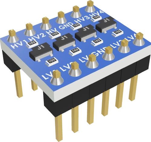
This 4-channel logic level converter (SparkFun BOB-12009 design and its clones) shifts digital signals both ways between a low-voltage and a high-voltage side, using one BSS138 MOSFET and two 10 kΩ pull-ups per channel (SparkFun Logic_Level_Bidirectional schematic). Wire LV to 3.3 V, HV to 5 V, GND to the common ground, the 3.3 V device to LV1 to LV4 and the 5 V device to the matching HV1 to HV4; both supplies are required and HV must be higher than LV (SparkFun hookup guide). It suits I2C at up to 400 kbit/s (NXP AN10441, p. 3), serial and slow SPI, but it is digital only and cannot drive loads.
The bi-directional logic level converter is a tiny board with four identical channels, each built from one N-channel BSS138 MOSFET and two 10 kΩ pull-up resistors: one to the low-voltage supply LV and one to the high-voltage supply HV (SparkFun Logic_Level_Bidirectional schematic). The FET's gate sits on LV, its source on the LVn pin and its drain on the HVn pin. Makers use it to connect a 3.3 V board such as an ESP32 or Raspberry Pi Pico to 5 V parts such as an I2C LCD, or a 5 V Arduino to a 3.3 V sensor, without either side seeing the other's voltage.
The circuit is NXP's classic I2C level shifter (AN10441, pp. 3, 4). When nothing pulls a line low, the FET is off and each side rests high at its own supply through its own pull-up, which is the level shift. When the low side pulls the line down, the FET's gate-source voltage rises past its threshold and it conducts, pulling the high side low too. When the high side pulls down, the FET's body diode drags the low side down until the FET turns on. Every channel therefore works in both directions with no direction pin, as an open-drain, wired-AND line.
Because a high level is only ever a 10 kΩ pull-up, the board shifts logic, not power: it cannot light an LED or drive a relay, and it cannot carry an analog voltage (the SparkFun hookup guide calls it purely digital). NXP rates the technique for Standard-mode and Fast-mode I2C, up to 400 kbit/s (AN10441, p. 3). HV must be equal to or higher than LV in normal operation (p. 4), and SparkFun states the board also works with 2.8 V and 1.8 V devices on the low side (product page). The BSS138's gate threshold is 0.5 V to 1.5 V (Diodes DS30144, p. 2), which is why LV can go that low.
Logic Level Converter (4-ch) pinout
| Pin | Function | Type |
|---|---|---|
| LV1 | Digital | bidirectional |
| LV2 | Digital | bidirectional |
| LV | LV (low-voltage supply)1.8–5 V | power in |
| GND | GND | power in |
| LV3 | Digital | bidirectional |
| LV4 | Digital | bidirectional |
| HV1 | Digital | bidirectional |
| HV2 | Digital | bidirectional |
| HV | HV (high-voltage supply)1.8–5 V | power in |
| GND_2 | GND | power in |
| HV3 | Digital | bidirectional |
| HV4 | Digital | bidirectional |
How to wire the Logic Level Converter (4-ch)
Pin by pin, for the board you have.
| Logic Level Converter (4-ch) | Arduino Uno | Note |
|---|---|---|
| LV | 3V3 | |
| HV | 5V | |
| GND | GND | |
| LV1 | SDA | |
| LV2 | SCL | |
| LV3 | D2 | |
| LV4 | D3 | |
| HV1 | LCD 1602 I2C SDA | |
| HV2 | LCD 1602 I2C SCL | |
| HV3 | HC-SR04 TRIG | |
| HV4 | HC-SR04 ECHO | |
| LCD and HC-SR04 VCC | the 5 V rail that feeds HV | their GND to GND |
| Logic Level Converter (4-ch) | ESP32 DevKit V1 | Note |
|---|---|---|
| LV | 3V3 | |
| HV | VIN | |
| GND | GND | |
| LV1 | GPIO21 (D21) | |
| LV2 | GPIO22 (D22) | |
| LV3 | GPIO13 (D13) | |
| LV4 | GPIO14 (D14) | |
| HV1 | LCD 1602 I2C SDA | |
| HV2 | LCD 1602 I2C SCL | |
| HV3 | HC-SR04 TRIG | |
| HV4 | HC-SR04 ECHO | |
| LCD and HC-SR04 VCC | the 5 V rail that feeds HV | their GND to GND |
- HV is on VIN, which gives about 5 V only while the board is powered from USB.
| Logic Level Converter (4-ch) | Raspberry Pi Pico | Note |
|---|---|---|
| LV | 3V3 | |
| HV | VBUS | |
| GND | GND | |
| LV1 | GP4 | |
| LV2 | GP5 | |
| LV3 | GP14 | |
| LV4 | GP15 | |
| HV1 | LCD 1602 I2C SDA | |
| HV2 | LCD 1602 I2C SCL | |
| HV3 | HC-SR04 TRIG | |
| HV4 | HC-SR04 ECHO | |
| LCD and HC-SR04 VCC | the 5 V rail that feeds HV | their GND to GND |
- HV is on VBUS, which gives about 5 V only while the board is powered from USB.
Logic Level Converter (4-ch) code
Every example here compiles for its board.
// Logic Level Converter (4-ch) on Raspberry Pi Pico: wiring and a free simulation at https://www.tinkered.ai/components/logic-level-converter
#include <Arduino.h>
#include <Wire.h>
#include <LiquidCrystal_I2C.h>

LiquidCrystal_I2C lcd(0x27, 16, 2);
const int TRIG = 14, ECHO = 15;   // through channels 3 and 4

void setup() {
  Serial.begin(115200);
  Wire.begin();                   // GP4 SDA, GP5 SCL, through channels 1 and 2
  lcd.init();                     // the library's entry point: starts Wire and the 16x2 display
  lcd.backlight();
  lcd.print("3V3 <-> 5V ok");
  pinMode(TRIG, OUTPUT);
  pinMode(ECHO, INPUT);
}

void loop() {
  digitalWrite(TRIG, LOW);
  delayMicroseconds(2);
  digitalWrite(TRIG, HIGH);
  delayMicroseconds(10);
  digitalWrite(TRIG, LOW);
  float cm = pulseIn(ECHO, HIGH, 30000) / 58.0;
  lcd.setCursor(0, 1);
  lcd.print("Dist ");
  lcd.print(cm, 1);
  lcd.print(" cm   ");
  Serial.println(cm, 1);
  delay(200);
}
Before you wire it
- LV to the 3.3 V side's supply (the 3.3 V board's 3V3), HV to the 5 V side's supply (5V, a Pico's VBUS, an ESP32's VIN), GND to the common ground. All three, always: a channel carries nothing without both supplies.
- Everything on the 3.3 V side goes to LVn, everything on the 5 V side to HVn. A channel joins exactly one line: LV1 with HV1, LV2 with HV2, and so on.
- I2C: SDA through one channel and SCL through another. The board already has a 10 kΩ pull-up on each side of each channel, so add no others. Power the I2C part from its own side's supply.
- One channel per signal, both directions: an HC-SR04's TRIG through one channel, its ECHO back through another; a 5 V UART's TX and RX through two.
- Power each part from the supply of the side it is on: a 5 V LCD from 5 V, a 3.3 V sensor from 3V3.
- No LV on 5 V and HV on 3.3 V (swapped): no channel works, and the 3.3 V side sees 5 V.
- No 5 V board's pin on an LVn pin, and NO 3.3 V board's pin on an HVn pin: the pull-up lifts the 3.3 V pin to 5 V.
- No WS2812 / NeoPixel data through it: its slow rising edge garbles the 0.4 µs bits. Use a 74AHCT125 buffer powered from 5 V.
- No analog signal through it (a potentiometer, an LDR, a sensor's AO): it only shifts HIGH and LOW. Divide a 5 V analog signal with resistors instead.
- No fast SPI (a TFT at 20-40 MHz) through it: use a 74LVC245 or the display's own 3.3 V input.
- Connect all three supply pins every time: LV to the low-voltage rail (3.3 V), HV to the high-voltage rail (5 V) and GND to the common ground. SparkFun says a steady, regulated voltage on both is required (hookup guide), and the FET gates take their bias from LV (schematic).
- Keep HV equal to or higher than LV (NXP AN10441, p. 4). Swapped, the 3.3 V side is pulled toward 5 V through its pull-ups and no channel shifts.
- Put the 3.3 V device's pins on LV1 to LV4 and the 5 V device's pins on the matching HV1 to HV4: LV1 pairs with HV1, LV2 with HV2, and so on.
- For I2C, run SDA through one channel and SCL through another. Each side already has a 10 kΩ pull-up per channel (schematic), so extra pull-ups are usually unnecessary; a module's own pull-ups simply sit in parallel. Keep the bus at 100 or 400 kHz (AN10441, p. 3).
- Each channel carries one signal. A UART needs two channels (TX one way, RX the other), and an HC-SR04 needs one for TRIG and one for ECHO.
- Power each device from its own side: a 5 V LCD from HV's rail, a 3.3 V sensor from LV's rail.
Specifications
- Channels
- 4, each bi-directionalSparkFun Bi-Directional Logic Level Converter hookup guide
- Per channel
- One BSS138 N-channel MOSFET, 10 kΩ pull-up to LV and 10 kΩ pull-up to HVSparkFun Logic_Level_Bidirectional schematic (BOB-12009)
- Supplies
- LV and HV both required, regulated; HV higher than LVSparkFun hookup guide; NXP AN10441, p. 4
- Low-side devices
- Works with 3.3 V, 2.8 V and 1.8 V devicesSparkFun BOB-12009 product page
- I2C speed
- Standard mode (100 kbit/s) and Fast mode (400 kbit/s); not for Hs modeNXP AN10441, p. 3
- MOSFET gate threshold
- 0.5 V min, 1.2 V typ, 1.5 V maxDiodes BSS138 datasheet DS30144, p. 2
- MOSFET ratings
- VDS 50 V, ID 200 mA continuousDiodes BSS138 datasheet DS30144, p. 2
- Pinout
- LV1, LV2, LV, GND, LV3, LV4 on one row; HV1, HV2, HV, GND, HV3, HV4 on the otherSparkFun Logic_Level_Bidirectional schematic
- Board size
- 0.63 × 0.52 in (16.05 × 13.33 mm)SparkFun BOB-12009 product page
- Supply voltage
- 1.8–5 V
- Dimensions
- 16.05 × 13.33 mmmaker's datasheet, checked 29 Oct 2026
- Weight
- 1.5 g
From the SparkFun BOB-12009 design (BSS138); generic clones's datasheet, published by SparkFun BOB-12009 design (BSS138); generic clones.
Common mistakes
Forgetting LV or HV
Each channel needs both supplies: the gate is biased from LV and each side's high level comes from its own pull-up (SparkFun schematic). With a supply missing, the channels do not shift correctly. Wire LV, HV and GND every time.
Swapping the LV and HV sides
A 5 V board's pin on LVn, or a 3.3 V board's pin on HVn, defeats the purpose: the HV pull-up lifts the 3.3 V pin to 5 V. The 3.3 V side always goes on LV, the 5 V side on HV, with HV at least as high as LV (NXP AN10441, p. 4).
Driving LEDs, buzzers or relays through it
A high on either side is only a 10 kΩ pull-up (SparkFun schematic), so it supplies a fraction of a milliamp. Drive loads from the board's own pin or a transistor, and use the converter for logic signals only.
Passing analog signals
SparkFun's guide says the converter is purely digital and cannot map an analog voltage from one range to another. Divide a 5 V analog sensor output with two resistors instead.
Pushing fast signals through it
Rising edges come from 10 kΩ pull-ups, so edges are slow. NXP rates the circuit for I2C up to 400 kbit/s (AN10441, p. 3); fast SPI displays and WS2812 LED data need a powered buffer such as a 74AHCT125 instead.
Logic Level Converter (4-ch) questions
How do I connect a 5 V I2C LCD to an ESP32 or Raspberry Pi Pico?
Wire LV to the board's 3.3 V, HV to 5 V (VIN on an ESP32 DevKit, VBUS on a USB-powered Pico) and GND to GND. Put the board's SDA and SCL on LV1 and LV2, the LCD's SDA and SCL on HV1 and HV2, and power the LCD from 5 V. NXP's MOSFET shifter is made for exactly this I2C use (AN10441, pp. 3, 4).
Does the logic level converter work in both directions?
Yes, every channel does. Whichever side pulls the line low, the other side follows through the MOSFET or its body diode, and when neither pulls low each side rests at its own supply (NXP AN10441, p. 4). That is why I2C, whose SDA line changes direction, works through it.
Why does my I2C scanner find nothing through the level shifter?
Check that LV, HV and GND are all connected, that HV is the higher voltage (AN10441, p. 4), and that each device sits on its own side: 3.3 V pins on LVn, 5 V pins on HVn. Also confirm SDA and SCL are on matching channel numbers on both sides.
Can I use it for SPI or UART?
Yes for UART and slower SPI: SparkFun shows serial and SPI hookups in its guide, using one channel per line. Because highs come through 10 kΩ pull-ups, keep speeds moderate; NXP characterises the circuit at up to 400 kbit/s (AN10441, p. 3). For a fast SPI display, use a buffer chip.
What is the lowest voltage it works with?
SparkFun states it works with 2.8 V and 1.8 V devices on the low side (product page). The BSS138's gate threshold is 0.5 V to 1.5 V (Diodes DS30144, p. 2), so the LV supply must sit comfortably above it for the FET to turn on.
Logic level converter vs a resistor divider: which should I use?
A two-resistor divider only steps a one-way signal down, such as a 5 V ECHO into a 3.3 V pin. The converter works both ways and also steps 3.3 V up to 5 V, which a divider cannot, so use it for I2C and any line that must be driven from the 3.3 V side (NXP AN10441, p. 4).
Build something with the Logic Level Converter (4-ch)
- Build this
5 V I2C LCD on an ESP32 or Pico
Run a 5 V LCD 1602 or 2004 backpack from a 3.3 V board through two channels for SDA and SCL.
- Build this
HC-SR04 on a 3.3 V board
Send TRIG up to 5 V on one channel and bring the 5 V ECHO back down on another.
- Build this
3.3 V sensor on an Arduino Uno
Read a 3.3 V-only I2C sensor from a 5 V Uno without exposing it to 5 V pull-ups.
- Build this
Mixed-voltage serial link
Connect a 3.3 V module's UART to a 5 V microcontroller with one channel for TX and one for RX.
This page as plain Markdown, for ChatGPT, Claude or your own agent. /components/logic-level-converter.md