PC817 Optocoupler
The PC817 is a 4-pin optocoupler that passes a signal through light across 5 kV of isolation, so a 12 V or 24 V circuit can talk to a microcontroller safely.
- Isolation voltage5 kV rms (AC, 1 min)
- LED forward voltage1.2 V typ, 1.4 V max at IF 20 mA
- LED current50 mA max continuous; 6 V max reverse voltage
- Collector-emitter voltage80 V max (emitter-collector 6 V max)
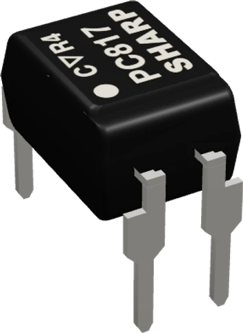
The Sharp PC817 is a DIP-4 photocoupler: an infrared LED (pin 1 anode, pin 2 cathode) lights a phototransistor (pin 4 collector, pin 3 emitter) across 5 kV rms of isolation (Sharp PC817XNNSZ0F sheet OP14004EN, pp. 1, 2). Drive the LED through a series resistor at a few milliamps (its forward voltage is 1.2 V typical at 20 mA, 50 mA absolute maximum, p. 3), put the emitter on the reading side's ground and the collector on a GPIO with a pull-up; the pin reads LOW while the LED is lit. Its collector takes up to 80 V and 50 mA (p. 3).
The PC817 is a general-purpose photocoupler from Sharp: an infrared emitting diode and an NPN phototransistor sealed face to face in a 4-pin DIP. Current through the LED makes light that turns the transistor on, while the two sides share no electrical connection; the isolation is rated at 5 kV rms (Sharp PC817XNNSZ0F sheet OP14004EN, pp. 1, 3). Makers use it to read a 12 V or 24 V signal such as a PLC output, a doorbell or an industrial sensor with a 3.3 V or 5 V board, or to switch another circuit from a GPIO while keeping the two grounds apart.
On the input side the LED drops 1.2 V typical (1.4 V max) at 20 mA and takes 50 mA continuous at most, with only 6 V of reverse voltage (datasheet, p. 3), so it always needs a series resistor. On the output side the transistor withstands 80 V collector to emitter and 50 mA of collector current (p. 3). How much current it sinks depends on the current transfer ratio (CTR): at 5 mA of LED current and 5 V across the transistor, the collector current is 2.5 mA to 30 mA, and Sharp sorts parts into ranks, rank C giving 10 mA to 20 mA, a CTR of 200 % to 400 % (pp. 3, 5).
The PC817 is built for logic-level signals at modest speed. Sharp gives a cut-off frequency of 80 kHz typical and rise and fall times of 4 µs and 3 µs typical (18 µs max) with a 100 Ω load (datasheet, p. 3); with the kilohm pull-ups used on a microcontroller input it switches more slowly. It suits switches, relays, zero-cross detection and slow pulses rather than fast serial buses. EL817 and LTV-817 parts from other makers share the same pinout.
PC817 Optocoupler pinout
| Pin | Function | Type |
|---|---|---|
| A | Digital | input |
| K | 2 Cathode | passive |
| E | 3 Emitter | passive |
| C | Digital | open collector |
How to wire the PC817 Optocoupler
Pin by pin, for the board you have.
| PC817 Optocoupler | Arduino Uno | Note |
|---|---|---|
| A | D7 | through a 1 kΩ resistor |
| K | GND | |
| C | D2 | |
| E | GND |
| PC817 Optocoupler | ESP32 DevKit V1 | Note |
|---|---|---|
| A | GPIO13 (D13) | through a 1 kΩ resistor |
| K | GND | |
| C | GPIO14 (D14) | |
| E | GND |
| PC817 Optocoupler | Raspberry Pi Pico | Note |
|---|---|---|
| A | GP0 | through a 1 kΩ resistor |
| K | GND | |
| C | GP1 | |
| E | GND |
PC817 Optocoupler code
Every example here compiles for its board.
// PC817 Optocoupler on Arduino Uno: wiring and a free simulation at https://www.tinkered.ai/components/pc817
const int LED_PIN = 7;   // PC817 pin 1 (anode) through 1 kOhm
const int OUT_PIN = 2;   // PC817 pin 4 (collector), pin 3 (emitter) to GND

void setup() {
  Serial.begin(9600);
  pinMode(LED_PIN, OUTPUT);
  pinMode(OUT_PIN, INPUT_PULLUP);   // the transistor only pulls down
}

void loop() {
  digitalWrite(LED_PIN, HIGH);
  delay(500);
  Serial.print("LED on:  output ");
  Serial.println(digitalRead(OUT_PIN) == LOW ? "LOW (conducting)" : "HIGH");
  digitalWrite(LED_PIN, LOW);
  delay(500);
  Serial.print("LED off: output ");
  Serial.println(digitalRead(OUT_PIN) == LOW ? "LOW" : "HIGH (off)");
}
// PC817 Optocoupler on ESP32 DevKit V1: wiring and a free simulation at https://www.tinkered.ai/components/pc817
const int LED_PIN = 13;   // PC817 pin 1 (anode) through 1 kOhm
const int OUT_PIN = 14;   // PC817 pin 4 (collector), pin 3 (emitter) to GND

void setup() {
  Serial.begin(9600);
  pinMode(LED_PIN, OUTPUT);
  pinMode(OUT_PIN, INPUT_PULLUP);   // the transistor only pulls down
}

void loop() {
  digitalWrite(LED_PIN, HIGH);
  delay(500);
  Serial.print("LED on:  output ");
  Serial.println(digitalRead(OUT_PIN) == LOW ? "LOW (conducting)" : "HIGH");
  digitalWrite(LED_PIN, LOW);
  delay(500);
  Serial.print("LED off: output ");
  Serial.println(digitalRead(OUT_PIN) == LOW ? "LOW" : "HIGH (off)");
}
// PC817 Optocoupler on Raspberry Pi Pico: wiring and a free simulation at https://www.tinkered.ai/components/pc817
const int LED_PIN = 0;   // PC817 pin 1 (anode) through 1 kOhm
const int OUT_PIN = 1;   // PC817 pin 4 (collector), pin 3 (emitter) to GND

void setup() {
  Serial.begin(9600);
  pinMode(LED_PIN, OUTPUT);
  pinMode(OUT_PIN, INPUT_PULLUP);   // the transistor only pulls down
}

void loop() {
  digitalWrite(LED_PIN, HIGH);
  delay(500);
  Serial.print("LED on:  output ");
  Serial.println(digitalRead(OUT_PIN) == LOW ? "LOW (conducting)" : "HIGH");
  digitalWrite(LED_PIN, LOW);
  delay(500);
  Serial.print("LED off: output ");
  Serial.println(digitalRead(OUT_PIN) == LOW ? "LOW" : "HIGH (off)");
}
Before you wire it
- A resistor in series with the LED, always (pin 1 or pin 2 side): a GPIO or supply straight across it destroys it.
- The LED's cathode (pin 2) to the ground of the circuit that drives it; the emitter (pin 3) to the ground of the circuit that reads it. To keep the isolation, do not join those two grounds.
- The collector (pin 4) to the GPIO that reads it, with pinMode(pin, INPUT_PULLUP) or a pull-up resistor to that board's 3.3 V / 5 V. It reads LOW when the LED is lit (active LOW).
- On a classic ESP32, GPIO34-39 have no pull-up: use another pin, or add a 10 kΩ pull-up to 3.3 V.
- No LED without its series resistor.
- No pull-down on the collector, no output read with INPUT alone and nothing pulling it up: it floats.
- Always put a resistor in series with the LED (pin 1 or pin 2 side). Size it for a few milliamps from the driving voltage minus about 1.2 V (Sharp sheet, p. 3): 1 kΩ from 5 V gives about 3.8 mA, and from 12 V about 2.2 kΩ gives a similar current. Never exceed the 50 mA absolute maximum (p. 3).
- Connect the cathode (pin 2) to the ground of the circuit that drives the LED and the emitter (pin 3) to the ground of the circuit that reads the output. Keep those two grounds separate if you want the isolation (5 kV rms, Sharp sheet, p. 3).
- Read the collector (pin 4) on a GPIO with a pull-up, either INPUT_PULLUP or a resistor to that board's 3.3 V or 5 V. The pin reads LOW while the LED is lit, so invert it in code.
- Choose a pull-up the transistor can pull down: the collector current available is the LED current times the CTR, at least 50 % at 5 mA on an unranked part and 200 % on rank C (Sharp sheet, pp. 3, 5). A 10 kΩ pull-up at 3.3 V needs only about 0.33 mA.
- If the input can be reversed, such as a field wire, add a diode across or in series with the LED: its reverse rating is only 6 V (Sharp sheet, p. 3).
- Keep signals slow. Sharp's 80 kHz cut-off is measured with a 100 Ω load (p. 3); with a 10 kΩ pull-up the edges are much slower, so reserve it for switches, relays and pulses of a few kHz.
- Sharp gives an 80 kHz cut-off frequency with a 100 Ω load.
Specifications
- Isolation voltage
- 5 kV rms (AC, 1 min)Sharp PC817XNNSZ0F sheet OP14004EN, p. 3
- LED forward voltage
- 1.2 V typ, 1.4 V max at IF 20 mASharp PC817XNNSZ0F sheet OP14004EN, p. 3
- LED current
- 50 mA max continuous; 6 V max reverse voltageSharp PC817XNNSZ0F sheet OP14004EN, p. 3 (absolute maximum)
- Collector-emitter voltage
- 80 V max (emitter-collector 6 V max)Sharp PC817XNNSZ0F sheet OP14004EN, p. 3
- Collector current
- 50 mA maxSharp PC817XNNSZ0F sheet OP14004EN, p. 3
- Current transfer
- IC 2.5 to 30 mA at IF 5 mA, VCE 5 V (CTR 50 % to 600 %); rank C 10 to 20 mA (200 % to 400 %)Sharp PC817XNNSZ0F sheet OP14004EN, pp. 3, 5
- Saturation voltage
- 0.1 V typ, 0.2 V max at IF 20 mA, IC 1 mASharp PC817XNNSZ0F sheet OP14004EN, p. 3
- Speed
- Cut-off 80 kHz typ; rise 4 µs, fall 3 µs typ (18 µs max) at RL 100 ΩSharp PC817XNNSZ0F sheet OP14004EN, p. 3
- Pinout
- 1 anode, 2 cathode, 3 emitter, 4 collectorSharp PC817XNNSZ0F sheet OP14004EN, p. 2
- Operating temperature
- -30 to 100 °CSharp PC817XNNSZ0F sheet OP14004EN, p. 3
- Maximum supply voltage
- 80 V
- Forward voltage
- 1.2 V
- Dimensions
- 4.58 × 6.5 × 4.02 mm
- Weight
- 0.23 g
From the Sharp (PC817C; EL817C, LTV-817C equivalents)'s datasheet, published by Sharp (PC817C; EL817C, LTV-817C equivalents).
Common mistakes
No resistor on the LED
Driving pins 1 and 2 straight from a GPIO or a supply pushes the LED past its 50 mA absolute maximum (Sharp sheet, p. 3). Always add a series resistor sized for a few milliamps.
Collector and emitter swapped
With the emitter on the GPIO and the collector on ground, the phototransistor is reversed; its emitter-collector rating is only 6 V (Sharp sheet, p. 3) and it does not switch properly. Pin 4 is the collector and goes to the GPIO and pull-up; pin 3 is the emitter and goes to ground.
No pull-up on the output
The phototransistor only pulls the line low. Without INPUT_PULLUP or an external pull-up resistor the pin floats while the LED is off. On a classic ESP32, GPIO34 to GPIO39 are input only with no internal pull-up (Espressif ESP32 datasheet), so add a resistor there.
Joining the two grounds
Tying the LED-side ground to the microcontroller ground removes the isolation the part exists to provide. Keep the two sides separate unless you only need level translation.
Using it for fast serial data
With rise and fall times of 4 µs and 3 µs typical, up to 18 µs (Sharp sheet, p. 3), and slower still behind a kilohm pull-up, the PC817 smears fast UART, I2C or SPI edges. Use a high-speed digital isolator for those.
PC817 Optocoupler questions
How do I wire a PC817 to an Arduino?
Drive the LED from a digital pin through a 1 kΩ resistor into pin 1, with pin 2 to that side's ground. Connect pin 3 (emitter) to the reading board's GND and pin 4 (collector) to a digital pin set to INPUT_PULLUP (Sharp sheet, p. 2). The pin reads LOW while the LED is lit.
Can I use the PC817 with an ESP32 or other 3.3 V board?
Yes, on both sides. A 3.3 V GPIO can light the LED through about 330 Ω to 470 Ω, since it drops about 1.2 V (Sharp sheet, p. 3). On the output side, pull the collector up to 3.3 V, not 5 V, so the GPIO never sees more than its own supply.
How do I read a 12 V or 24 V signal with a PC817?
Put the 12 V or 24 V signal through a series resistor into pin 1 and return pin 2 to that circuit's ground, sizing the resistor for a few milliamps after the LED's 1.2 V drop (Sharp sheet, p. 3): about 2.2 kΩ at 12 V. Read pin 4 with a pull-up on the microcontroller side; the two grounds stay apart.
Why does my PC817 output never go LOW?
Either the LED is not lit, because it is reversed, unpowered or missing its return path, or the pull-up is stiffer than the transistor can sink. The collector current available is the LED current times the CTR, as little as 50 % at 5 mA on an unranked part (Sharp sheet, p. 3), so a 1 kΩ pull-up with a 1 mA LED current will not pull down. Use a 10 kΩ pull-up or more LED current.
What does the letter after PC817 mean?
It is the CTR rank. At 5 mA of LED current Sharp's ranks give collector currents of 4 to 8 mA (A), 6.5 to 13 mA (B), 10 to 20 mA (C) and 15 to 30 mA (D) (Sharp sheet, p. 5). The common PC817C is rank C, a CTR of 200 % to 400 %.
PC817 vs a relay: which should I use?
Use the PC817 to pass a signal across isolation: it switches 50 mA at most on its output (Sharp sheet, p. 3) but has no contacts to wear and switches in microseconds. Use a relay when you need to switch a real load such as a lamp or a pump.
Build something with the PC817 Optocoupler
- Build this
Isolated 12 V or 24 V input
Read a PLC output, an industrial proximity sensor or a 24 V limit switch on a 3.3 V or 5 V microcontroller with the grounds kept apart.
- Build this
Doorbell or alarm sensor
Detect when an existing 12 V doorbell or alarm circuit fires without wiring it into the microcontroller's supply.
- Build this
Isolated relay driver input
Trigger a relay module's input through an optocoupler so motor or coil noise stays off the microcontroller's ground.
- Build this
Camera shutter or remote trigger
Close a camera's or a device's remote-trigger contacts from a GPIO with no electrical connection between the two.
This page as plain Markdown, for ChatGPT, Claude or your own agent. /components/pc817.md